
Datasheet


13
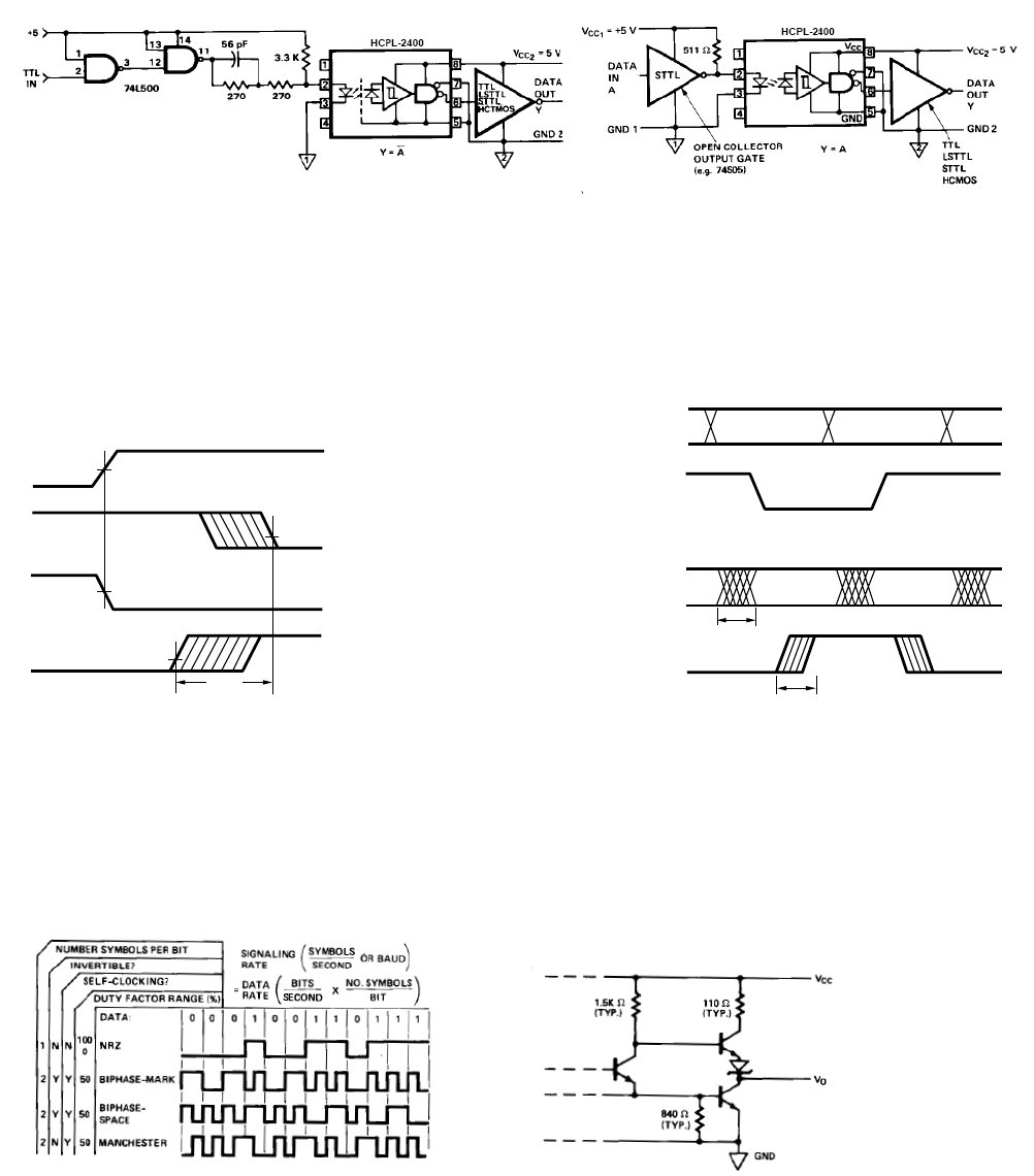
Figure 15. Illustration of propagation delay skew – t
PSK
.
50%
1.5 V
I
F
V
O
50%I
F
V
O
t
PSK
1.5 V
HCPL-2400 fig 15
Figure 13. Recommended 20 MBd HCPL-2400/30 interface circuit.
Applications
Figure 14. Alternative HCPL-2400/30 interface circuit.
Figure 16. Parallel data transmission example.
Figure 17. Modulation code selections.
Figure 18. Typical HCPL-2400/30 output schematic.
HCPL-2400 fig 16
DATA
t
PSK
INPUTS
CLOCK
DATA
OUTPUTS
CLOCK
t
PSK