
Datasheet


12
Optical Isolation for Field Bus Networks
To recognize the full benets of these networks, each
recommends providing galvanic isolation using Avago
optocouplers. Since network communication is bi-direc-
tional (involving receiving data from and transmitting
data onto the network), two Avago optocouplers are
needed. By providing galvanic isolation, data integrity is
retained via noise reduction and the elimination of false
signals. In addition, the network receives maximum pro-
tection from power system faults and ground loops.
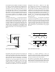
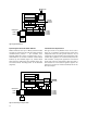
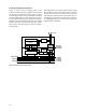
Within an isolated node, such as the DeviceNet Node
shown in Figure 18, some of the node’s components are
referenced to a ground other than V- of the network.
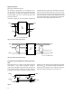
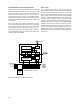
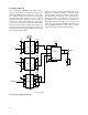
Figure 17. Typical eld bus communication physical model.
These components could include such things as devices
with serial ports, parallel ports, RS232 and RS485 type
ports. As shown in Figure 18, power from the network is
used only for the transceiver and input (network) side of
the optocouplers.
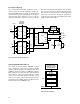
Isolation of nodes connected to any of the three types of
digital eld bus networks is best achieved by using the
HCPL-x710 optocouplers. For each network, the HCPL-
x710 satisify the critical propagation delay and pulse
width distortion requirements over the temperature
range of 0°C to +85°C, and power supply voltage range
of 4.5 V to 5.5 V.
Digital Field Bus Communication Networks
To date, despite its many drawbacks, the 4 - 20 mA
analog current loop has been the most widely accepted
standard for implementing process control systems.
In today’s manufacturing environment, however,
automated systems are expected to help manage
the process, not merely monitor it. With the advent
of digital eld bus communication networks such as
DeviceNet, PROFIBUS, and Smart Distributed Systems
(SDS), gone are the days of constrained information.
Controllers can now receive multiple readings from eld
devices (sensors, actuators, etc.) in addition to diagnos-
tic information.
The physical model for each of these digital eld bus
communication networks is very similar as shown in
Figure 17. Each includes one or more buses, an interface
unit, optical isolation, transceiver, and sensing and/or
actuating devices.
CONTROLLER
TRANSCEIVER
OPTICAL
ISOLATION
BUS
INTERFACE
TRANSCEIVER
OPTICAL
ISOLATION
BUS
INTERFACE
TRANSCEIVER
OPTICAL
ISOLATION
BUS
INTERFACE
TRANSCEIVER
OPTICAL
ISOLATION
BUS
INTERFACE
TRANSCEIVER
OPTICAL
ISOLATION
BUS
INTERFACE
FIELD BUS
XXXXXX
YYY
SENSOR
DEVICE
CONFIGURATION
MOTOR
STARTER
MOTOR
CONTROLLER
HCPL-0710 fig 16