
Datasheet


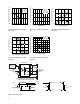
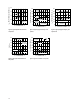

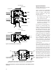


Figure 24. CMOS gate drive circuit for HCPL-261A/-261N families.Figure 23. TTL open-collector/open drain gate drive circuit for
HCPL-261A/-261N families.
820 Ω
HCPL-�261A fig 22
1
3
2
4
V
CC
74HC00
(OR ANY
OPEN-COLLECTOR/
OPEN-DRAIN
LOGIC GATE)
HCPL-261X
LED
750 Ω
HCPL-�261A fig 23
1
3
2
4
V
CC
74HC04
(OR ANY
TOTEM-POLE
OUTPUT LOGIC
GATE)
HCPL-261A/261N
1N4148
LED
Propagation Delay, Pulse-Width Distortion and Propa-
gation Delay Skew
Propagation delay is a gure of merit which describes
how quickly a logic signal propagates through a sys-
tem. The propagation delay from low to high (t
PLH
) is the
amount of time required for an input signal to propa-
gate to the output, causing the output to change from
low to high. Similarly, the propagation delay from high
to low (t
PHL
) is the amount of time required for the input
signal to propagate to the output, causing the output to
change from high to low (see Figure 9).
Pulse-width distortion (PWD) results when t
PLH
and t
PHL
dier in value. PWD is dened as the dierence between
t
PLH
and t
PHL
and often determines the maximum data
rate capability of a transmission system. PWD can be
expressed in percent by dividing the PWD (in ns) by the
minimum pulse width (in ns) being transmitted. Typi-
cally, PWD on the order of 20-30% of the minimum pulse
width is tolerable; the exact gure depends on the par-
ticular application (RS232, RS422, T-1, etc.).
Propagation delay skew, t
PSK
, is an important parameter
to consider in parallel data applications where synchro-
nization of signals on parallel data lines is a concern. If
the parallel data is being sent through a group of opto-
couplers, dierences in propagation delays will cause
the data to arrive at the outputs of the optocouplers at
dierent times. If this dierence in propagation delay
is large enough it will determine the maximum rate at
which parallel data can be sent through the optocou-
plers.
Propagation delay skew is dened as the dierence be-
tween the minimum and maximum propagation delays,
either t
PLH
or t
PHL
, for any given group of optocouplers
which are operating under the same conditions (i.e., the
same drive current, supply voltage, output load, and op-
erating temperature). As illustrated in Figure 25, if the in-
puts of a group of optocouplers are switched either ON
or OFF at the same time, t
PSK
is the dierence between
the shortest propagation delay, either t
PLH
or t
PHL
, and the
longest propagation delay, either t
PLH
or t
PHL
.
As mentioned earlier, t
PSK
can determine the maximum
parallel data transmission rate. Figure 26 is the timing
diagram of a typical parallel data application with both
the clock and the data lines being sent through opto-
couplers.
Table 1. Eects of Common Mode Pulse Direction on Transient I
LED
If |I
LP
| < |I
LN
|, If |I
LP
| > |I
LN
|,
LED I
F
Current LED I
F
Current
If dV
CM
/dt Is: then I
LP
Flows: and I
LN
Flows: Is Momentarily: Is Momentarily:
positive (>0) away from LED away from LED increased decreased
anode through C
LA
cathode through C
LC
negative (<0) toward LED toward LED decreased increased
anode through C
LA
cathode through C
LC