
Datasheet


7
Absolute Maximum Ratings
Parameter Symbol Min. Max. Units
Storage Temperature T
S
-55 125 °C
Operating Temperature T
A
-40 85 °C
Average Input Current I
F(AVG)
20 mA
Reverse Input Voltage V
R
5 V
Input Power Dissipation P
I
45 mW
Supply Voltage (1 Minute Maximum) V
CC
7 V
Output Collector Current I
O
50 mA
Output Collector Voltage V
O
7 V
Output Collector Power Dissipation P
O
85 mW
Lead Solder Temperature T
LS
260°C for 10 sec.
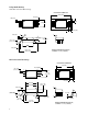
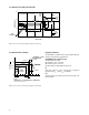
Solder Reow Temperature Prole See Package Outline Drawings section
Recommended Operating Conditions
Parameter Symbol Min. Max. Units
Input Current, Low Level I
FL
0 250 µA
Input Current, High Level I
FH
5 15 mA
Power Supply Voltage V
CC
4.5 5.5 V
Operating Temperature T
A
- 40 85 °C
Fan Out (at R
L
= 1 kΩ) N 5 TTL Loads
Output Pull-up Resistor R
L
330 4k Ω
Electrical Specications (DC)
Over recommended operating conditions unless otherwise specied. All typicals at V
CC
= 5 V, T
A
= 25 °C.
Parameter Symbol Min. Typ. Max. Units Test Conditions Fig. Note
High Level Output Current I
OH
5.5 100 µA V
CC
= 5.5 V, 1
V
O
= 5.5 V, I
F
= 250 µA
Input Threshold Current I
TH
2.0 5.0 mA V
CC
= 5.5 V, V
O
= 0.6 V, 13
I
OL
> 13 mA
Low Level Output Voltage V
OL
0.35 0.6 V V
CC
= 5.5 V, I
F
= 5 mA, 2, 4,
I
OL(Sinking)
= 13 mA 5,13
High Level Supply Current I
CCH
4 7.5 mA V
CC
= 5.5 V, I
F
= 0 mA,
Low Level Supply Current I
CCL
6 10.5 mA V
CC
= 5.5 V, I
F
= 10 mA,
Input Forward Voltage V
F
1.4 1.5 1.75 V T
A
= 25 °C I
F
= 10 mA 3
1.3 1.8
Input Reverse Breakdown Voltage BV
R
5 V I
R
= 10 µA
Input Capacitance C
IN
60 pF f = 1 MHz, V
F
= 0 V
Input Diode Temperature ∆V
F
/∆T
A
-1.6 mV/°C I
F
= 10 mA 12
Coecient
All typicals at T
A
= 25°C, V
CC
= 5 V