
Datasheet


12
CMR with the LED On (CMR
H
)
A high CMR LED drive circuit must keep the LED on during
common mode transients. This is achieved by overdriving
the LED current beyond the input threshold so that it is not
pulled below the threshold during a transient. A minimum
LED current of 7 mA provides adequate margin over the
maximum I
FLH
of 5 mA to achieve 10 kV/µs CMR.
LED Drive Circuit Considerations for Ultra High CMR Per-
formance
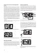
Without a detector shield, the dominant cause of optocou-
pler CMR failure is capacitive coupling from the input side
of the optocoupler, through the package, to the detector
IC as shown in Figure 19. The ACPL-P302/W302 improves
CMR performance by using a detector IC with an optically
transparent Faraday shield, which diverts the capacitively
coupled current away from the sensitive IC circuitry. How-
ever, this shield does not eliminate the capacitive coupling
between the LED and optocoupler pins 5-8 as shown in
Figure 20. This capacitive coupling causes perturbations
in the LED current during common mode transients and
becomes the major source of CMR failures for a shielded
optocoupler. The main design objective of a high CMR
LED drive circuit becomes keeping the LED in the proper
state (on or o) during common mode transients. For ex-
ample, the recommended application circuit (Figure 17),
can achieve 10 kV/µs CMR while minimizing component
complexity.
Techniques to keep the LED in the proper state are dis-
cussed in the next two sections.
Figure 21. Equivalent Circuit for Figure 15 During Common Mode Transient.
The open collector drive circuit, shown in Figure 22, can
not keep the LED o during a +dV
CM
/dt transient, since all
the current owing through C
LEDN
must be supplied by the
LED, and it is not recommended for applications requiring
ultra high CMR
L
performance. The alternative drive circuit
which like the recommended application circuit (Figure
17), does achieve ultra high CMR performance by shunting
the LED in the o state.
C
LEDP
C
LEDN
61
52
43
C
LEDP
C
LEDN
61
52
43
C
LEDP
C
LEDN
61
52
43
SHIELD
C
LED01
C
LED02
C
LEDP
C
LEDN
61
52
43
SHIELD
C
LED01
C
LED02
C
LEDP
C
LEDN
61
52
43
SHIELD
I
LEDP
R
g
V
CC
= 18V
+
-
0.1 µF
+
-
THE ARROWS INDICATE THE DIRECTION
OF CURRENT FLOW DURING - dV
CM
/ dt
+ 5 V
V
SAT
+
-
V
CM
I
+
-
+
-
V
SAT
+
-
V
SAT
+
-
•
•
Figure 19. Optocoupler Input to Output Capacitance Model for Unshielded Optocou-
plers.
Figure 20. Optocoupler Input to Output Capacitance Model for Shielded Optocouplers.
Figure 22. Not Recommended Open Collector Drive Circuit.
C
LEDP
C
LEDN
61
52
43
SHIELD
I
LEDN
+5 V
Q1
C
LEDP
C
LEDN
61
52
43
SHIELD
I
LEDN
+5 V
Q1Q1
CMR with the LED O (CMR
L
)
A high CMR LED drive circuit must keep the LED o (V
F
≤
V
F(OFF)
) during common mode transients. For example,
during a -dV
CM
/dt transient in Figure 21, the current ow-
ing through C
LEDP
also ows through the R
SAT
and V
SAT
of
the logic gate. As long as the low state voltage developed
across the logic gate is less than V
F(OFF)
the LED will remain
o and no common mode failure will occur.
C
LEDP
C
LEDN
61
52
43
SHIELD
+5 V
C
LEDP
C
LEDN
61
52
43
+5 V
Figure 23. Recommended LED Drive Circuit for Ultra-High CMR Dead Time and Propa-
gation Delay Specications.