
Specifications

e-mail:
support@broadcasttools.com
voice:
360.854.9559
fax:
866.783.1742
9
SS 4x4 Installation and Operation Manual
INSTALLATION
Mounting
The SS 4.4 is designed to be rack mounted in a standard 19” rack. It should be
mounted in an area that is accessible from the rear and preferably away from sources
of heat. We recommend before permanently installing the SS 4.4, you bench test and
become familiar with the operation of the unit.
Power Supply Connection
Insert the universal AC input, multi-voltage DC switching power supply’s 5-pin DIN
connector into the power receptacle on the rear panel of the SS 4.4. When ready,
plug the power supply into the appropriate AC receptacle.
CAUTION! Only use the power supply provided with this product.
Connecting the audio inputs, outputs and remote control devices
It is recommended that all cables connected to the SS 4.4 be looped through ferrite
cores to suppress RF. Surge protection with RF filtering such as the Tripp Lite “ISO-
BAR 4” is also suggested for the power transformer. The purchase of an inexpensive
uninterruptible power supply (UPS) will provide back up AC in case of power out-
ages. Check out our web site for lightning protection links.
Connecting the audio Inputs and Outputs
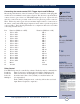
The input channels are numbered from 1 through 4 on the rear panel from left to
right. The SS 4.4 interfaces to your audio equipment through plug-in euroblock
screw terminals. Follow the legends for the desired audio input and output connec-
tions, which appear on the rear of the unit. Before installing a wire, remove the plug-
in euroblock screw terminal and turn each capture screw fully counterclockwise.
Strip each conductor to a length of 0.25” and insert the conductor fully into the ter-
minal. Turn the capture screw fully clockwise to secure the conductor.
The terminals accommodate wire sizes from 16 - 28 AWG solid or stranded wire.
Connections may be made to the + and - inputs for balanced operation, or to the +
input and grounding the - side for unbalanced input operation. The input impedance
is 22KΩ, 600Ω terminations may be installed on the connector if required.
Connections can be made to the + and - outputs for balanced operation, or to the +
output and ground for unbalanced output operation.
CAUTION! In no case should either the + or - OUTPUTS be connected to
ground.
CAUTION!
Installation of the SS
4.4 in high RF environ-
ments should be per-
formed with care.
Shielded cable is sug-
gested for all control,
audio inputs and out-
puts. All shields should
be tied to the “GND”
terminal on each chan-
nel. The station ground
should be connected to
the chassis ground
screw (GND) located on
each side of the chassis
as viewed from the rear.
For lightning protection
devices, check out
www.polyphaser.com
and www.itwlinx.com.