
Specifications

e-mail:
support@broadcasttools.com
voice:
360.854.9559
fax:
866.783.1742
10
SS 4x4 Installation and Operation Manual
INSTALLATION
Connecting the remote control, PIP / Trigger Inputs and OC/Relays
Most front panel functions of the SS 4.4 may be remote controlled via the pluggable
euroblock screw terminals located on the rear panel. The SS 4.4 accepts momentary
contact closures; open collector or TTL/CMOS input logic levels. Open collectors
and relay connections are provided on the lower rear panel 18 position connector
TB-6. Each relay and/or open collector and mute input is labeled. Connections to
the remote control and/or PIP (trigger) inputs are made on the top of the 18-position
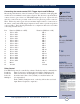
connector TB-6. The following information is a comparison chart to be used when
connecting external devices.
Pin Function (DIPSw 8 = OFF). Function (DIPSw 8 = ON)
1 IN 1 to OP 1 PIP 1
2 IN 2 to OP 1 PIP 2
3 IN 3 to OP 1 PIP 3
4 IN 4 to OP 1 PIP 4
5 IN 1 to OP 2 PIP 5
6 IN 2 to OP 2 PIP 6
7 IN 3 to OP 2 PIP 7
8 IN 4 to OP 2 PIP 8
9 IN 1 to OP 3 PIP 9
10 IN 2 to OP 3 PIP 10
11 IN 3 to OP 3 PIP 11
12 IN 4 to OP 3 PIP 12
13 IN 1 to OP 4 PIP 13
14 IN 2 to OP 4 PIP 14
15 IN 3 to OP 4 PIP 15
16 IN 4 to OP 4 PIP 16
17 Macro N/A
18 Ground Ground
Relay Control
Four SPDT relays may be controlled by software. Each relay may be commanded to:
Latch On Turns on and stays on (through power failures) until turned off.
Latch Off Turns off and stays off (through power failures) until turned on.
Pulse On Overrides latch; turns on for (default) second, then latches off.
Multiplex (See dipswitch 6)
In the (“MPX”) multiplex mode, each relay follows the associated
input channel assigned to output two.
!
TIP
Helpful tips area.
CAUTION!
Broadcast Tools
products, as any elec-
tronic device, can fail
...
NOTE:
For safety, DO NOT
connect ...
WEBSITE:
Visit our web site for
product updates and
additional information.