
Specifications
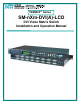


NTI VEEMUX DVI VIDEO MATRIX SWITCH
3
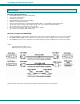
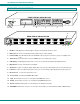
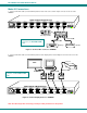
FEATURES AND FUNCTIONS
1. IR LED- for indicating when an infrared signal is being received from the IR remote control
2. IR Receiver- this receives the IR signal from the infrared remote control (optional)
3. Power/Standby- this LED indicates when the VEEMUX is either ready for user interface (green) or in standby mode
(red)
4. System Reset- press this button to cycle the VEEMUX processor and reboot the system
5. LCD Display- for indicating what inputs (video sources) are connected to the labeled output (display device)
6. Menu buttons- used to control LCD menu navigation
7. Out buttons- used to select which outputs (display devices) to connect to which inputs (video sources) when pressed
8. In buttons- used to select which inputs (video sources) to connect to which outputs (display devices) when pressed
9. IEC Connector- for connection of AC power cord
10. Power Switch- for turning the VEEMUX ON or OFF
11. Input- DVI-I Female connector- for connecting to DVI/HDMI video sources
12. Output- DVI-I Female connector- for connecting to DVI/HDMI display devices
13. RS232 connector- RJ45 female- for connecting the user's RS232 control cable
14. ETHERNET- RJ45 female connector- for connection of CAT5 cable to Local Area Network (LAN) for WEB interface
FRONT VIEW OF SM-8X8-DVI-LCD
IR
System
Reset
12
4
3
5678
12
4
3
5678
NTI
R
Network Techno logies In c
R
VEEMUX
Menu In
Out
RJ45
"<USB>"
RJ45
"<USB>"
FUSE T2A,250V
AC INPUT 100-240VAC,30W
INPUT 1INPUT 6INPUT 7INPUT 8 INPUT 5 INPUT 2INPUT 3INPUT 4
RS232
ETHERNET(DCE)
OUTPUT 1OUTPUT 2OUTPUT 3OUTPUT 4OUTPUT 5OUTPUT 6OUTPUT 7OUTPUT 8
REAR VIEW OF SM-8X8-DVI-LCD
1234 5 6 7 8
910 11
12
13 14
OUT: 1 2 3 4
IN: 1 2 3 4