
Specifications


NTI VEEMUX DVI VIDEO MATRIX SWITCH
28
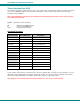
SS_01- Enable Auto Status Mode
Command:
Byte 1 Byte 2 Byte 3 Byte 4 Byte 5 Byte 6
‘S’
(0x53)
‘S’
(0x53)
Space
(0x20)
‘0’
(0x30)
‘1’
(0x31)
<CR>
(0x0D)
Response:
Byte 1 Byte 2
‘∗’
(0x2A)
<CR>
(0x0D)
Auto status mode is disabled by default whenever the connection is established, and this command must be entered to enable it.
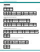
When auto status mode is enabled, a message will be sent whenever an input/output connection changes from any source. The
format of this message is given in the table below. The first two numeric digits are the output port number and the two after the
colon are the number of the input port that is now connected to it.
Byte 1 Byte 2 Byte 3 Byte 4 Byte 5 Byte 6 Byte 7 Byte 8 Byte 9
‘p’
(0x70)
‘c’
(0x63)
Space
(0x20)
Output – 1st digit
(0x30…0x32)
Output – 2nd digit
(0x30…0x39)
‘:’
(0x3A)
Input – 1st digit
(0x30…0x32)
Input – 2nd digit
(0x30…0x39)
<CR>
(0x0D)
SS_00- Disable Auto Status Mode
Command:
Byte 1 Byte 2 Byte 3 Byte 4 Byte 5 Byte 6
‘S’
(0x53)
‘S’
(0x53)
Space
(0x20)
‘0’
(0x30)
‘0’
(0x30)
<CR>
(0x0D)
Response:
Byte 1 Byte 2
‘∗’
(0x2A)
<CR>
(0x0D)
This command disables auto status mode.
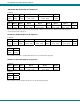
SX- Examine connections
Command:
Byte 1 Byte 2 Byte 3
‘S’
(0x53)
‘X’
(0x58)
<CR>
(0x0D)
Response:
Multiple lines, one line for each output:
Byte 1 Byte 2 Byte 3 Byte 4 Byte 5 Byte 6 Byte 7 Byte 8 Byte 9
‘p’
(0x70)
‘c’
(0x63)
Space
(0x20)
Output – 1st digit
(0x30…0x32)
Output – 2nd digit
(0x30…0x39)
‘:’
(0x3A)
Input – 1st digit
(0x30…0x32)
Input – 2nd digit
(0x30…0x39)
<CR>
(0x0D)
Byte 1 Byte 2 Byte 3 Byte 4 Byte 5 Byte 6 Byte 7 Byte 8 Byte 9
‘p’
(0x70)
‘c’
(0x63)
Space
(0x20)
Output – 1st digit
(0x30…0x32)
Output – 2nd digit
(0x30…0x39)
‘:’
(0x3A)
Input – 1st digit
(0x30…0x32)
Input – 2nd digit
(0x30…0x39)
<CR>
(0x0D)
Last line:
Byte 1 Byte 2
‘∗’
(0x2A)
<CR>
(0x0D)