
Specifications
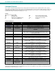

NTI VEEMUX DVI VIDEO MATRIX SWITCH
22
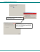
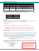
SerTest- RS232 Interface Test Program
This software allows a user to test the functions of an NTI server switch, matrix switch or Multi-user/Multi-platform switch RS232
interface. The SerTest program is automatically loaded when installing the Matrix Switcher’s Control Program as described
above. The SerTest program, located in the NTI program group, generates a main menu with the 4 selections described below:
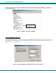
Main Options
• Matrix Operations
- send commands to the matrix unit.
• Ethernet Operations
- set Ethernet connection variables
• Setup Options
- set COM port, baud rate, and unit address
• About SerTest
- display the program version
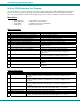
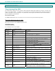
Matrix Operations
Key Selection Description
1) Connect Video Output/User to an Input/CPU - connect an output to an input
2) Connect All Video Outputs/Users to an Input/CPU - connect all outputs to an input
3) Connect Audio Output/User to an Input/CPU - connect an output to an input (audio ports only)
4) Connect All Audio Outputs/Users to an Input - connect all outputs to an input (audio ports only)
5) Change Mute Status for Audio Output/User - mute or un-mute the Audio port output
6) Change Volume for Audio Output/User - change Audio port output volume
7) Read Connection for Video Output/User -read the connection of a specific video output
8) Read Connection for Audio Output/User -read the connection of a specific audio output
9) Read Mute and Volume for Audio Output/User - read the volume and the mute status of the specified output
(audio ports only)
a) Save I/O Connections into Unit Memory -save the connections into switch memory bank
b) Restore I/O Connections from Unit Memory -restore the connections from switch memory bank
c) Change All Units Baud Rate (9600/COM1:) -change RS-232 Baud rate of all switches
-the current baud rate and serial port are displayed in
parentheses
d) Reset Unit - send a reset command to the switch
- the current unit address is displayed in parentheses
e) Reset All Units - send an internal reset command to all switches
f) Read Unit Size - read the switch size (number of inputs and outputs)
g) Read Unit Version/Revision String -read a string containing the switch version, type, and size
h) Save All Units I/O Connections into Units Memory -save the connections into switch memory bank, command for all
switches
i) Restore All Units I/O Connections from Units Memory -restore the connections from switch memory bank, command for
all switches
Grayed keys are for models with audio support
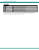
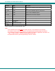
Ethernet Operations
Key Selection Description
1) Set Unit IP Address - enter the desired IP address in xxx.xxx.xxx.xxx format
- number of digits is minimum 1 and maximum 3 for each field. Leading zeroes are
accepted
2) Set Unit Subnet Mask
- enter the desired IP address in xxx.xxx.xxx.xxx format
- number of digits is minimum 1 and maximum 3 for each field. Leading zeroes are
accepted
3) Set Unit Default Gateway - enter the desired default gateway
- number of digits is minimum 1 and maximum 3 for each field. Leading zeroes are
accepted
4) Set Unit Website Timeout
- set the website timeout; timeout = numeric string of timeout in seconds
- Values: 60, 300, 600, 900, 1800, 3600, 7200, 18000, 28800 0 = no timeout
5) Read Unit IP Address - read the unit IP address in xxx.xxx.xxx.xxx format
6) Read Unit Subnet Mask - read the unit subnet mask in xxx.xxx.xxx.xxx format
7) Read Unit Default Gateway - read the unit default gateway in xxx.xxx.xxx.xxx format
8) Read Unit Website Timeout - read the current website timeout period in seconds
- Values: 60, 300, 600, 900, 1800, 3600, 7200, 18000, 28800 0 = no timeout