
User manual


Table Of Contents
- User Manual
- Starlink SL9003Q
- Digital Studio Transmitter Link
- WARRANTY
- SL9003Q Manual Dwg # 602-12016-01 R: G Revision Levels:
- Using This Manual - Overview
- Section 1 System Features and Specifications
- Section 2 Quick Start
- Section 3 Installation
- Section 4 Operation
- Section 5 Module Configuration
- Section 6 Customer Service
- Section 7 System Information
- Table of Contents
- List of Figures
- List of Tables
- 1 System Features and Specifications
- 2 Quick Start
- 3 Installation
- 4 Operation
- 7.1 Introduction
- 7.2 Front Panel Operation
- 4.3 Screen Menu Navigation and Structure
- 7.4 Screen Menu Summaries
- 4.4.1 Meter
- 4.4.2 System: Card View
- 4.4.3 System: Power Supply
- 4.4.4 System: Info
- 4.4.5 System: Basic Card Setup
- 4.4.6 Factory Calibration
- 4.4.7 SYSTEM: UNIT-WIDE PARAMS
- 4.4.8 System: Date/Time
- 4.4.9 System: Transfer
- 4.4.10 System: External I/O (NMS)
- 4.4.11 Alarms/Faults
- 4.4.12 Radio: Modem Status (QAM)
- 4.4.13 Radio TX Status
- 4.4.14 Radio RX Status
- 4.4.15 Radio TX Control
- 4.4.16 Radio RX Control
- 4.4.17 Radio Modem (QAM) Configure
- 4.4.18 Radio TX Configure
- 4.4.19 Radio RX Configure
- 4.4.20 Radio Modem/TX/RX Copy Function
- 4.5 Intelligent Multiplexer PC Interface Software
- 4.6 NMS/CPU PC Interface Software
- 5 Module Configuration
- 6 Customer Service
- 7 System Description
- 8 Appendices
- Appendix A: Path Evaluation Information
- Appendix B: Audio Considerations
- Appendix C: Glossary of Terms
- Appendix D: Microvolt – dBm – Watt Conversion (50 ohms)
- Appendix E: Spectral Emission Masks
- Appendix F: Redundant Backup with TP64 and TPT-2 Transfer Panels
- Appendix G: Optimizing Radio Performance For Hostile Environments
- Appendix H: FCC APPLICATIONS INFORMATION - FCC Form 601
- Starlink SL9003Q & Digital Composite - 950 MHz Band
3-18 Section 3: Installation
Moseley SL9003Q 602-12016 Revision G
edges to avoid damage. A kinked line indicates damage, so the damaged piece must be
removed and a splice installed to couple the pieces together.
3.4.3. Environmental Seals
The connections at the antenna and the transmission line must be weather-sealed. This
is best accomplished by completely wrapping each connection with Scotch #70 tape (or
equivalent), pulling the tape tight as you wrap to create a sealed boot. Then, for
mechanical protection over the sealed layer, completely wrap the connection again with
Scotch #88 (or equivalent). Tape ends must be cut rather than torn—a torn end will
unravel and work loose in the wind. Use plenty of tape for protection against water
penetration and the premature replacement of the transmission line.
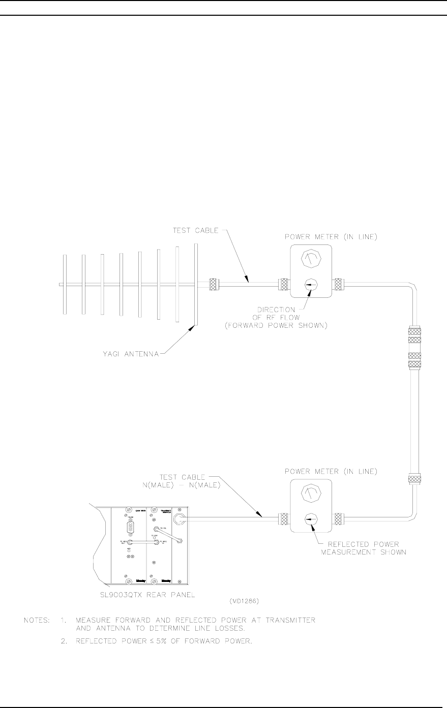
Figure 3-7 Transmitter Antenna Testing