
User manual


Table Of Contents
- User Manual
- Starlink SL9003Q
- Digital Studio Transmitter Link
- WARRANTY
- SL9003Q Manual Dwg # 602-12016-01 R: G Revision Levels:
- Using This Manual - Overview
- Section 1 System Features and Specifications
- Section 2 Quick Start
- Section 3 Installation
- Section 4 Operation
- Section 5 Module Configuration
- Section 6 Customer Service
- Section 7 System Information
- Table of Contents
- List of Figures
- List of Tables
- 1 System Features and Specifications
- 2 Quick Start
- 3 Installation
- 4 Operation
- 7.1 Introduction
- 7.2 Front Panel Operation
- 4.3 Screen Menu Navigation and Structure
- 7.4 Screen Menu Summaries
- 4.4.1 Meter
- 4.4.2 System: Card View
- 4.4.3 System: Power Supply
- 4.4.4 System: Info
- 4.4.5 System: Basic Card Setup
- 4.4.6 Factory Calibration
- 4.4.7 SYSTEM: UNIT-WIDE PARAMS
- 4.4.8 System: Date/Time
- 4.4.9 System: Transfer
- 4.4.10 System: External I/O (NMS)
- 4.4.11 Alarms/Faults
- 4.4.12 Radio: Modem Status (QAM)
- 4.4.13 Radio TX Status
- 4.4.14 Radio RX Status
- 4.4.15 Radio TX Control
- 4.4.16 Radio RX Control
- 4.4.17 Radio Modem (QAM) Configure
- 4.4.18 Radio TX Configure
- 4.4.19 Radio RX Configure
- 4.4.20 Radio Modem/TX/RX Copy Function
- 4.5 Intelligent Multiplexer PC Interface Software
- 4.6 NMS/CPU PC Interface Software
- 5 Module Configuration
- 6 Customer Service
- 7 System Description
- 8 Appendices
- Appendix A: Path Evaluation Information
- Appendix B: Audio Considerations
- Appendix C: Glossary of Terms
- Appendix D: Microvolt – dBm – Watt Conversion (50 ohms)
- Appendix E: Spectral Emission Masks
- Appendix F: Redundant Backup with TP64 and TPT-2 Transfer Panels
- Appendix G: Optimizing Radio Performance For Hostile Environments
- Appendix H: FCC APPLICATIONS INFORMATION - FCC Form 601
- Starlink SL9003Q & Digital Composite - 950 MHz Band
F-6 Appendix F: Redundant Backup
Moseley SL9003Q 602-12016 Revision G
N
L
G
!
AGAINST RISK OF FIRE,
REPLACE WITH SAME TYPE
FOR CONTINUED P ROTECTION
DISCONNECT LINE CORD
PRIOR TO M ODULE REM OVAL
OUTPUT VOLTAGE:
AND RATING OF FUSE
X
+12V
X
+5V
+15V
+28V
INPUT: 90-260V, 47-63Hz
12/15
CAUTION
AC P/S
5/28
65W
I/O
EXT
RESET
CPU
NMS
70 MHz
IN
DEMOD
OUT
70 MHz
TP
RX LOCK
TRUNK
QAM
DEMOD
RECEIVER
ANTENNA
ID#
LIN
CMPR
RIGHT
CH. 2
LEFT
CH. 1
AES/EBU
SPDIF
AUDIO DEC
Radio A - MAIN Default
Radio B - STANDBY Default
To
Left Channel
or AES/EBU
N
L
G
!
AGAINST RISK OF FIRE,
REPLACE WITH SAME TYPE
FOR CONTINUED PROTECTION
DISCONNECT LINE CORD
PRIOR TO MODULE REMOVAL
OUTPUT VOLTAGE:
AND RATING OF FUSE
X
+12V
X
+5V
+15V
+28V
INPUT: 90-260V, 47-63Hz
12/15
CAUTION
AC P/S
5/28
65W
I/O
EXT
RESET
CPU
NMS
70 MHz
IN
DEMOD
OUT
70 MHz
TP
RX LOCK
TRUNK
QAM
DEMOD
RECEIVER
ANTENNA
ID#
LIN
CMPR
RIGHT
CH. 2
LEFT
CH. 1
AES/EBU
SPDIF
AUDIO DEC
COM-LEFT (-)
COM-LEFT (+)
COM-GROUND
COM-RIGHT (-)
COM-RIGHT (+)
1-LEFT (-)
1-LEFT (+)
1-GROUND
1-RIGHT (-)
1-RIGHT (+)
Broadcast Tools
SS 2.1/Terminal III
Switcher/Router
2-LEFT (-)
2-LEFT (+)
2-GROUND
2-RIGHT (-)
2-RIGHT (+)
Alt .
AES/
Left Ch.
2
3
1
2
3
1
XLR-Female-
to-Pigtail
2
3
1
2
3
1
2
3
1
2
3
1
1 (TB1)
TB4A
Switch Configuration:
SW5-6 = On
6
(RX_XFR_OUT - Blue)
7
(Ground - Black)
RJ45 8-Pin
to Pigtail
XLR-Female-
to-Pigtail
XLR-Male-
to-Pigtail
230-12416-
01
To
Right Channel
Alt .
AES/
Left Ch.
SL9003Q Receiver
SL9003Q Receiver
Antenna
ZAPD-21
Power
Splitter
3 (TB3)
2 (TB2)
RS-232
Data Sharing
Device
To
Remote
Control
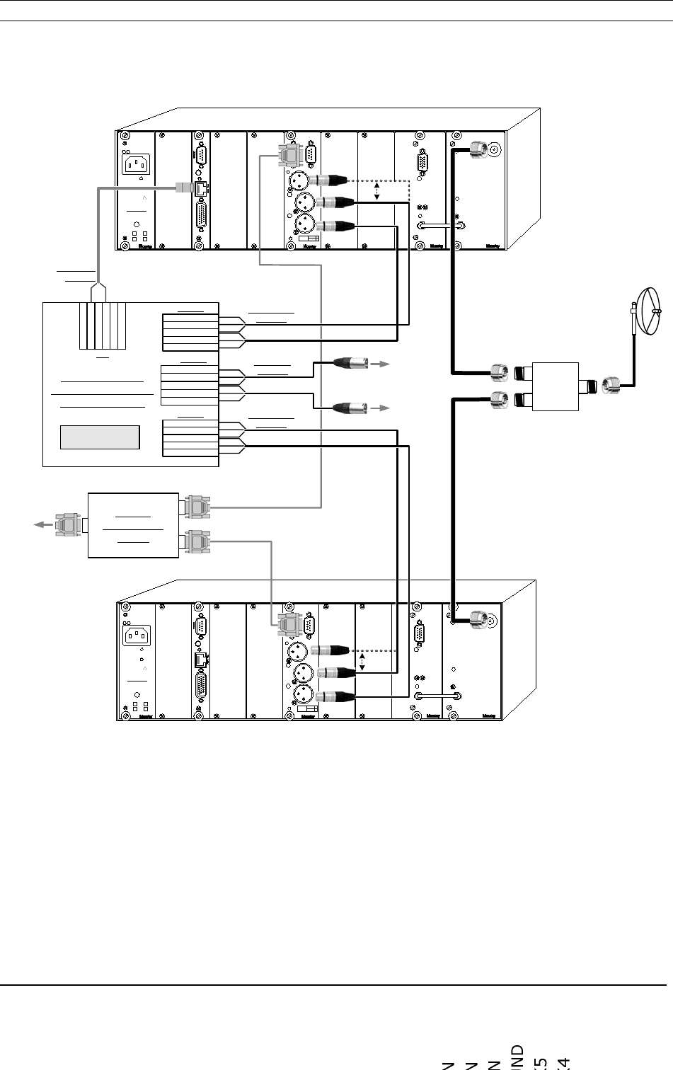
Figure 8-3 Receiver Audio Output Switching-External Control (Discrete or Digital Audio)
The router directs one of two balanced input pairs to the common balanced output. In a typical
application the router is rack mounted between main and standby receivers. Figure F-3 shows
the configuration for discrete audio. For digital audio outputs only, the left or right channel may
be substituted with the AES/EBU channel.
The Main Receiver provides control logic from the RJ45 connector (XFER) on the NMS card for
switching signal the switcher/router. The Main receiver control line (RJ45 pin 6) will be HIGH
(+5V) to indicate the Main receiver is healthy and router input 1 will be selected. If the Main