
User manual


Table Of Contents
- User Manual
- Starlink SL9003Q
- Digital Studio Transmitter Link
- WARRANTY
- SL9003Q Manual Dwg # 602-12016-01 R: G Revision Levels:
- Using This Manual - Overview
- Section 1 System Features and Specifications
- Section 2 Quick Start
- Section 3 Installation
- Section 4 Operation
- Section 5 Module Configuration
- Section 6 Customer Service
- Section 7 System Information
- Table of Contents
- List of Figures
- List of Tables
- 1 System Features and Specifications
- 2 Quick Start
- 3 Installation
- 4 Operation
- 7.1 Introduction
- 7.2 Front Panel Operation
- 4.3 Screen Menu Navigation and Structure
- 7.4 Screen Menu Summaries
- 4.4.1 Meter
- 4.4.2 System: Card View
- 4.4.3 System: Power Supply
- 4.4.4 System: Info
- 4.4.5 System: Basic Card Setup
- 4.4.6 Factory Calibration
- 4.4.7 SYSTEM: UNIT-WIDE PARAMS
- 4.4.8 System: Date/Time
- 4.4.9 System: Transfer
- 4.4.10 System: External I/O (NMS)
- 4.4.11 Alarms/Faults
- 4.4.12 Radio: Modem Status (QAM)
- 4.4.13 Radio TX Status
- 4.4.14 Radio RX Status
- 4.4.15 Radio TX Control
- 4.4.16 Radio RX Control
- 4.4.17 Radio Modem (QAM) Configure
- 4.4.18 Radio TX Configure
- 4.4.19 Radio RX Configure
- 4.4.20 Radio Modem/TX/RX Copy Function
- 4.5 Intelligent Multiplexer PC Interface Software
- 4.6 NMS/CPU PC Interface Software
- 5 Module Configuration
- 6 Customer Service
- 7 System Description
- 8 Appendices
- Appendix A: Path Evaluation Information
- Appendix B: Audio Considerations
- Appendix C: Glossary of Terms
- Appendix D: Microvolt – dBm – Watt Conversion (50 ohms)
- Appendix E: Spectral Emission Masks
- Appendix F: Redundant Backup with TP64 and TPT-2 Transfer Panels
- Appendix G: Optimizing Radio Performance For Hostile Environments
- Appendix H: FCC APPLICATIONS INFORMATION - FCC Form 601
- Starlink SL9003Q & Digital Composite - 950 MHz Band
Section 7: System Description 7-11
Moseley SL9003Q 602-12016 Revision G
7.7.3. Intelligent Multiplexer
The MUX is documented in a separate user manual. Typical broadcast applications are
described here:
4-Port Mux:
For composite STL systems, the 4-port mux (with composite option card) is used to route and
demultiplex the composite signal from the QAM demodulator.
6-Port Mux:
For discrete STL systems, the 6-port mux (with Ethernet option card) is primarily used to
interface and demultiplex the Ethernet data stream from the QAM demodulator.
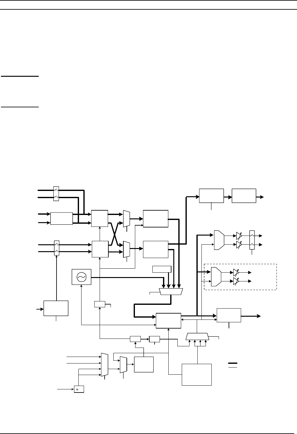
7.7.4. Audio Decoder
FIFOs
13107.2
PLL
R
L
DECODER
SOURCE
Analog Out Daughtercard
FRAME
SYNC
LINEAR
M4
R1,R2
ZEROES
CLOCK
DEMUX
16384
16
M5,M6
1024
1024
1024- 1536
32- 384
TRUNK COMPRESSED
TRUNK LINEAR
MUX COMPRESSED
MUX LINEAR
R6
M4
TRUNK
LINEAR
M3
D1-D5
DATA
AUX ASYNC
24576
OSCs
33868.8
XTAL
LEVEL
XLATORS
FIFOs
A9- A2
MUX
ADDRESS
DECODE
ADDRESS
MUX
GENERATOR
SINE
M1,M2
CONVERTER
SAMPLE
RATE
S81
AES/EBU
SPDIF
L & R
DIGITAL
AUDIO
D/A
D/A
R
L
Analog Audio
LINEAR
MUX
COMPRESSED
MUX
COMPRESSED
TRUNK
LINEAR
MODEM
COMPRESSED
MODEM
ASYNC
CONVERTER
SYNC TO
TRANSLATOR
RS-232
Front
Panel
Bargraph
DDS
DDSX2
I_R4
I_R1
I_R3
I_R2
M7,M8
ALL FREQUENCIES IN kHz
DATA
CLOCK
(MD1283)
Figure 7-9 Audio Decoder Block Diagram