
User manual


Table Of Contents
- User Manual
- Starlink SL9003Q
- Digital Studio Transmitter Link
- WARRANTY
- SL9003Q Manual Dwg # 602-12016-01 R: G Revision Levels:
- Using This Manual - Overview
- Section 1 System Features and Specifications
- Section 2 Quick Start
- Section 3 Installation
- Section 4 Operation
- Section 5 Module Configuration
- Section 6 Customer Service
- Section 7 System Information
- Table of Contents
- List of Figures
- List of Tables
- 1 System Features and Specifications
- 2 Quick Start
- 3 Installation
- 4 Operation
- 7.1 Introduction
- 7.2 Front Panel Operation
- 4.3 Screen Menu Navigation and Structure
- 7.4 Screen Menu Summaries
- 4.4.1 Meter
- 4.4.2 System: Card View
- 4.4.3 System: Power Supply
- 4.4.4 System: Info
- 4.4.5 System: Basic Card Setup
- 4.4.6 Factory Calibration
- 4.4.7 SYSTEM: UNIT-WIDE PARAMS
- 4.4.8 System: Date/Time
- 4.4.9 System: Transfer
- 4.4.10 System: External I/O (NMS)
- 4.4.11 Alarms/Faults
- 4.4.12 Radio: Modem Status (QAM)
- 4.4.13 Radio TX Status
- 4.4.14 Radio RX Status
- 4.4.15 Radio TX Control
- 4.4.16 Radio RX Control
- 4.4.17 Radio Modem (QAM) Configure
- 4.4.18 Radio TX Configure
- 4.4.19 Radio RX Configure
- 4.4.20 Radio Modem/TX/RX Copy Function
- 4.5 Intelligent Multiplexer PC Interface Software
- 4.6 NMS/CPU PC Interface Software
- 5 Module Configuration
- 6 Customer Service
- 7 System Description
- 8 Appendices
- Appendix A: Path Evaluation Information
- Appendix B: Audio Considerations
- Appendix C: Glossary of Terms
- Appendix D: Microvolt – dBm – Watt Conversion (50 ohms)
- Appendix E: Spectral Emission Masks
- Appendix F: Redundant Backup with TP64 and TPT-2 Transfer Panels
- Appendix G: Optimizing Radio Performance For Hostile Environments
- Appendix H: FCC APPLICATIONS INFORMATION - FCC Form 601
- Starlink SL9003Q & Digital Composite - 950 MHz Band
Section 5: Module Configuration 5-21
Moseley SL9003Q 602-12016 Revision G
5.9.3. Relay Mapping Configuration
5.9.3.1. Mapping Set 1 and “Map Faults-Relays” Set ON
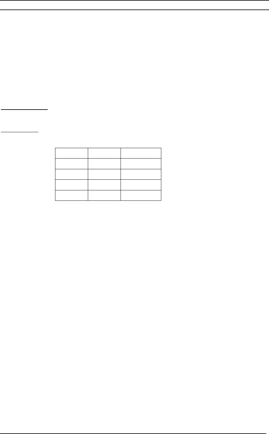
The analog output is selected by connecting pins 17 and 18 to ground pins 19-23 in the
order shown below:
Analog Output:
Ext I/O pin 10
Digital Input
(external I/O connector):
#18 #17 OUTPUT
Open
Open BER
Ground
Open RSL
Open
Ground FWD PWR
Ground
Ground REV PWR
To set the mapping, perform the following steps (refer to section 4.4.10 for
corresponding menu screens):
On the SL9003Q Tx Main Menu
Use Up or Down arrow to select System
<Enter>
Scroll down to Unit-Wide Parameters
<Enter>
Scroll up once then down twice to select Mapping
<Enter>
Use left or right arrow to select setting 0, 1 or 2
<Enter>
<Escape>
<Escape>
Use left or right arrow to select Yes to save settings
<Enter>