
Installation & Operating Guide


13
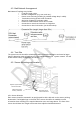
4.7
Electrical Connections
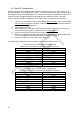
Refer to the vehicle manufacturer or bodybuilder guidelines for installation procedures and
connectivity in all applications. The sensor pinout is shown in the table below and connector
details given in section9:
Deutsch
Pin
Signal
Name
Brigade
Wire Colour
1
Ground
Brown
2
CAN High
Green
3
Positive (+12/+24V)
Yellow
4
CAN Low
Blue
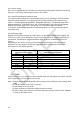
4.8
Power Input
Power must be applied to the BS-9100 sensor network via a dedicated Brigade power cable.
Only one power input to the system is permitted and must be suitably positioned within the
network to ensure that loading from all sensors is balanced and excessive voltage drops are
avoided.
The network must be adequately powered under all operating conditions. The installer must
verify that any volt drop throughout the network does not cause the supply at the sensor to
drop below the minimum recommended value during operation.
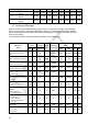
A single fuse must be installed per network. Multiple fuses are not permitted. The table in
section 4.9 provides power consumption data and fusing recommendations for various
network sizes under a range of supply voltages.