
Installation & Operating Guide


11
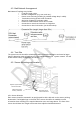
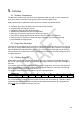
Adjustment Angle
In Horizontal Plane
Brigade Logo Readable,
Normal Orientation
Cable Exit Direction
Pointing To Bottom
4.3
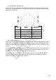
Bad Network Arrangement
Bad Network Topology may include:
o Long bus length >30m.
o Non-bus configuration (e.g. star, mesh etc.).
o Power at one end only (resulting in possible voltage drop in cable).
o Termination missing at both ends of network.
o Omission of Network Terminator cable.
o Extension cable between sensor and Y-Cable.
o Connection to more than 8 sensors on single bus.
o Connection to other CAN nodes, (not shown below).
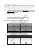
Example 3 (Bad), host connection at end of bus.
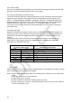
4.4
Test Site
The system test site should be relatively flat without excessive deviation and must be larger
than the detection range of each sensor in the intended Backsense
®
system network. This will
enable a basic setup, configuration and testing.
4.5
Sensor Mounting and Location
4.5.1 Sensor Direction
Each sensor should be mounted in an upright position with cable exit on the sensor pointing
downwards. The Brigade logo on the front of the sensor should be in readable, normal
orientation when standing in the required detection area, see image above. The front of the
sensor should have line of sight to all areas where objects should be detected.