
Installation & Operating Guide


10
4
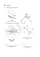
Hardware Installation
4.1
Recommended Network Layouts and Limitations
Backsense
®
BS-9100 Systems installation must adhere to a strict network topology to ensure
reliable communications between all sensors and host.
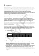
The network topology must represent a bus featuring 120Ω termination at both ends. Sensors
must be connected to the bus via Network Y-Cable only. The user must not install any
extension cable between the sensor and the Y-Cable. Examples for good and bad network
arrangements are show below:
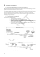
4.2
Good Network Arrangement
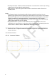
Good Network Topology Includes:
o 120Ω Termination at both ends
o Bus Length limited to 30m between terminations
o Power input position balanced depending on the sensor’s physical
distribution on the bus. This should be optimised to minimise voltage drop
over the cable for each sensor.
o No extension cables installed between the sensor and the Y-Cable. Only
sensor tail cable to Y-Cable is allowed.
Example 1 (Good), host connection at end of bus
Example 2 (Good), host connection in middle of bus