
Instruction manual

9
MobileMAX
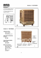
Section 6 - REPLACEMENT PARTS
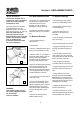
Ensure all electrical
connections are tight. Loose
connections cause overheating
which can result in machine
malfunction or fires.
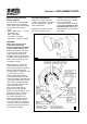
The main junction box includes
plug receptacles for the fire
protection system, fan motor and
water pump (see Fig. 14, page 15).
Note: The cord to the fire
protection system must be
plugged in before the cooler will
operate. Any attempt to tamper
with, or disable the fire
protection system will render
the cooler inoperative.
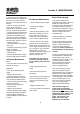
NOTE: SMALL BLOWER HOUSING
ILLUSTRATED
8
NOTE: SMALL BLOWER HOUSING
ILLUSTRATED
9
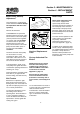
WARNING:
High voltage inside. Only use
the screws supplied to replace
the lid covering
external terminals.
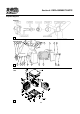
Fan Bearing Replacement
Sometimes a fan shaft bearing will
fail and must be replaced in the
field. Before removal of the
bearings, ensure you have a
Bearing Kit (Part No. 800523).
The following procedure should be
ahered to (see Fig. 27, and parts
list):
To Remove Bearings
• Ensure electric power is
disconnected.
• Remove belt.
• Remove small black plastic pin in
pulley (use screwdriver as lever).
• Remove pulley. As you begin to
extract the pulley depress the two
bearing mount clips together
(located inside the pulley boss) to
allow it to slide along the shaft.
• Remove the black plastic bearing
lock covering the bearing hub.
(Use home-made tool from 3"
diameter plastic pipe with notches
cut to engage the cap), twisting it
counter clockwise to remove.
• Use same tool to remove lock on
other side of fan.
• Place a flat screwdriver across
the corner of the bearing mount.
Hit the screwdriver with a hammer
until the bearing mount cracks.
Once the part has cracked pull it
from the bearing with a pair of
pliers.
• Remove the bearing and its
rubber resilient mount.
To Replace Bearings
• Fit new bearing/s over plastic
square-to-round bearing mounts.
• Fit the rubber resilient mounts
over the bearing/s.
• Clean the shaft and use a
lubricant on the shaft for re-
assembly
• Push the bearing assemly back
up to its housing
• Ensure bearing clips are in place.
• Engage the bearing lock into its
housing and twist it clockwise to
lock.
• Push the pulley back onto the
shaft, making sure the small hole
in the pulley lines up with the small
hole in the shaft. Insert clip
• Push the drive end bearing
assembly hard up to its housing.
• Engage the bearing lock into the
housing and twist it clockwise to
lock.
• Using a block of wood and
hammer, carefully drift the non-
drive bearing assembly back on
the shaft and into its housing until
the plastic locator tap pops into its
locating hole in the shaft.
• Replace the bearing lock (see
previous instructions).
• Carefully centre the fan on the
shaft and replace the plastic pins in
the shaft either side of the fan.