
Installation Instruction
2
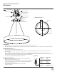
Plastic Anchor
Junction Box Screw
Mounting Screw
Canopy
Driver
Cable Gripper
Mounting Back Plate
Back Plate Dimensions
Ground Wire Screw
Junction Box
Wood Screw
Wire Connector
Ground Wire
D1
A1
E1
B1
C1
FIG. 1
PREPARATION
1. Shut o the power at the circuit breaker and remove existing xture, including the crossbar.
2. Carefully unpack your new xture and lay out all the parts on a clear area. Be careful not to lose any small parts necessary for installation.
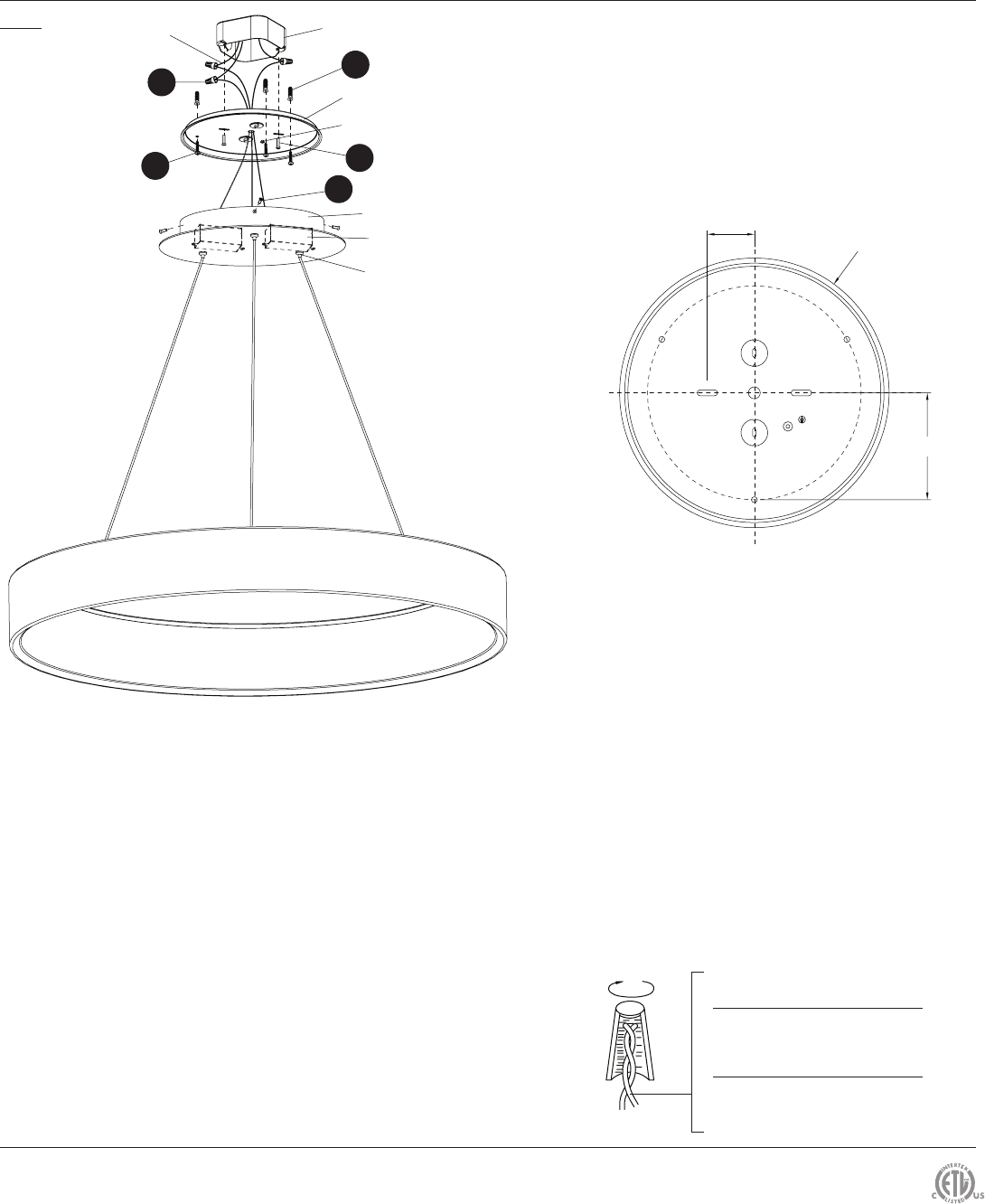
CONNECTING THE WIRES (Fig. 2)
3. Remove the mounting screws (C1) from the canopy.
4. Adjust the xture wire length by pushing the cable grippers on the canopy and pulling the wires as desired. Make sure the wires are
the same length.
5. Connect the Driver input wires with junction box wires as shown in Fig. 2, making sure that all wire connectors (A1) are secured.
If your outlet box has a green or bare copper ground wire, connect the xture’s ground wire to it. Otherwise, connect the xture’s ground
wire directly to the mounting plate using the green screw provided. After wires
are connected, tuck them carefully inside the junction box.
MOUNTING THE FIXTURE (Fig. 1)
6. Drill holes in the ceiling aligned with key holes located in the mounting
back plate, insert the plastic anchors (E1).
7. Secure the mounting plate to the junction box using junction box screws (B1),
fasten it to the wall using wood screw (D1). The side of the mounting back
plate marked “GND” must face out.
8. Place the xture over the mounting plate and secure it with
mounting screws (C1).
Fixture Wires
Black or
Smooth
Fixture Wires
White or
Ribbed
Fixture Wires
Bare wire
(Ground)
House Wires
Black
(Hot)
House Wires
White
(Neutral)
H
ouse Wires
Green or Bare Copper
(Ground)
Fig. 2 Wiring
Ø
8 15/16"
1 9/16"
3 9/16"
INSTALLATION INSTRUCTION
LED Pendant