
Installation & Assembly


INSTALLATION INSTRUCTIONS
W A R N I N G ! S H U T P O W E R O F F AT F U S E O R C I R C U I T B R E A K E R .
AVERTISSEMENT! COUPER LE COURANT AU NIVEAU DES FUSIBLES OU DU DISJONCTEUR.
Page 2/2
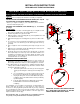
Fig. 4
Fig. 5
Fig. 6
MOUNTING THE FIXTURE, HARDWIRE VERSION (Fig. 4
& Fig. 6)
1. Shut off power at the circuit breaker and remove the old
fixture including the mounting hardware.
2. Carefully unpack your new fixture and lay out all the parts
on a clear area. Take care not to lose any small parts
necessary for installation.
3. Remove knockout tabs (1, 2, 3, 4, and 5) from mounting
plate (A) with a screwdriver or pliers.
4. Remove screw (F) and metal plate (G) from fixture body
(D) by using a screwdriver (not included). (Fig.6)
5. Loosen the wire connecters located inside the fixture
backplate and carefully remove the power cord and
bushing.
6. Secure mounting plate (A) to the outlet box using
mounting screws (C) (Size: #8-32N*L0.5”).
CONNECTING THE WIRES (Fig. 5)
7. Connect the electrical wires as shown in Fig. 5, making
sure that all wire connectors are secured. If your outlet
has a ground wire (green or bare copper), connect the
fixture’s ground wire to it.
FINISHING THE INSTALLATION (Fig. 4)
8. Align fixture body (D) onto mounting plate (A) and secure
with screws (B).
9. Insert plug (E) into the hole in fixture body (D).
10. Align the holes on small glass shade (R) and large glass
shade (S) onto lamp head (L) and with studs (T).
Your installation is now complete. Return power to the outlet
box and test the fixture.
Note: Illustration (Fig. 4) on this manual is for installation
purposes only. It may or may not be identical to the
fixture purchased.
IMPORTANT: FIXTURE SHOULD BE INSTALLED
BY A QUALIFIED ELECTRICIAN TO ENSURE
PROPER WIRING AND INSTALLATION.
FIXTURE
WIRES
Black or
Smooth
HOUSE
WIRES
Black
(Hot)
FIXTURE
WIRES
White or
Ribbed
HOUSE
WIRES
White
(Neutral)
FIXTURE
WIRES
Bare
Copper
(Ground)
HOUSE
WIRES
Green
(Ground)
G
F
D
E
1
2
5
Touch Switch
R
S
T
D
B
L
C
Wire Connector
UL Knob
Busing
A
TDC Power
3
4
-Mounting plate
-Ground Screw
-Mounting Screw*2
READ AND SAVE THESE INSTRUCTIONS