
Manual

16
O & M
ASME CLASS 600 & 900
A Division of Bray International, Inc.
The Ultimate Critical Service Triple Offset Valve
Operation and Maintenance Manual
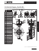
3. Loosen up all the disc seal ring retaining cap screws
(C8) but leave them in the valve with the disc seal
ring retainer (C7) attached to the disc (C1).
4. Completely open the valve, remove the disc seal
ring retaining cap screws (C8), extract the disc seal
ring retainer (C7) and the disc seal ring with collar
(C2 & C3) making sure not to damage the seat.
If it’s necessary, open the valve past 90° to easily
remove the seal retainer and disc seal ring. Using
soft tools and a suitable wire brush, carefully clean
any remnants of old gasket and foreign matter from
the face of the disc (C1). Blow out all threaded
holes and the gasket groove with compressed air.
remove any small scratches or product deposits (if
any).
6. Rotate the disc (C1) to it’s previous position to
facilitate installation of the disc seal ring (C2).
Place a new disc seal ring gasket (C3) into the
groove on the disc face (C1). The mating side of
the disc seal ring gasket can be lightly greased to
improve retention in the groove. Be sure that the
new disc seal ring (C2) is assembled with the disc
seal ring collar (C3) and kept together with the disc
seal ring collar pin (C4). Place the disc seal ring and
collar onto the disc making sure the collar groove
is aligned with the disc seal ring reference button
(C6). Place the disc seal ring retainer (C7) over the
disc seal ring. Apply anti-seize compound to the
disc seal ring retaining cap screws (C8). All of the
cap screws (C8) need to be fully threaded into the
Lubricate the sealing surfaces of the disc seal ring
(C2) and the body seat (replaceable) (B1).
7. Cycle the valve with the actuator 2-3 times, only
closing the valve to the point where the disc seal
ring engages with the seat. Check each time that
the disc seal ring makes full contact with the body
seat (replaceable) without torquing into the seat.
Attention should be paid in the closing stroke that
the body seat (replaceable) does not scratch the disc
seal ring. This will allow the disc seal ring and seat
to be properly aligned. Tighten at least four screws
in the seal retainer to prevent the disc seal ring from
further movement. Open the valve approximately
seal ring, disc seal ring retainer) are aligned. Tighten
the disc seal ring retainer cap screws (C8) using
a cross bolting technique, to the 50% of torque
Table 4 (Pg. 16). Once all screws
are tightened at the same torque, proceed to fully
tighten them to 100% of the listed torque value.
8. Remove the gearbox (if installed), mount the valve
actuator and test the valve.
11.4 Bottom Flange Gasket Replacement
-
ence numbers. (Pg 13).
1. If the valve is installed, remove line pressure.
2. Completely remove the bottom plate screws (G3).
Remove the bottom plate (G1) and the bottom plate
gasket (G2).
3. Clean the bearing area of residual gasket and for-
eign materials. Grease the body/bottom plate gasket
groove area.
4. Place the new gasket (G2) on the bottom plate (G1)
and install it onto the body.
5. Reinstall the bottom plate screws (G3) and using the
cross bolting technique, tighten them according to
Table 7 (Pg. 17).
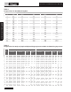
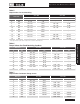
Table 4
Torque Values fordisc seal ring Retaining Cap Screws
Valve Size Class 600 Class 900
in mm Lb-in Nm Lb-in Nm
4 100 142 - 185 16 - 20 - –
6 150 265 - 310 30 - 35 310 - 350 35 - 40
8 200 265 - 310 30 - 35 490 - 530 55 - 60
10 250 795 - 885 90 - 100 1000 - 1120 115 - 130
12 300 795 - 885 90 - 100 - -
14 350 795 - 885 90 - 100 - -
16 400 795 - 885 90 - 100 1000 - 1120 115 - 130
18 450 1685 - 1815 190 - 205 1860 - 1995 215 - 225
20 500 - - 1860 - 1995 215 - 225