
User Manual

Installation and Maintenance Manual
Series 85 Ball Valves
Date: August 2011 / Page 2 of 2
®
A Subsidiary of BRAY INTERNATIONAL, Inc.
FLOW-TEK, Inc. Tel: 832.912.2300
© 2011 Flow-Tek, Inc.
8323 N. Eldridge Pkwy #100 Fax: 832.912.2301
Houston, Texas 77041 www.flow-tek.com
ASSEMBLY
1. Install the thrust washer on stem O.D.
2. Install stem packing in valve body.
3. Insert stem into body, taking care not to pinch or
nick stem packing.
4. Install seat in the rear of the body cavity with the
spherical curvature facing the mating ball.
5. Insert ball in body, care should be taken not to
scratch the ball during installation.
6. Insert seat in threaded end cap so that spherical
curvature is facing the ball. Tighten end cap
tightly.
7. Tighten packing sleeve nut.
8. Place handle on assembly and tighten stem nut.
9. Safe and proper bench testing is required before
re-installing to service. Ensure that valve operates
smoothly.
WARNING: DO NOT REMOVE ANY VALVE PARTS
WHILE LINE IS UNDER PRESSURE! UNDER NO
CIRCUMSTANCES! LINE MUST BE DEPRESSURIZED
BEFORE DEISASSEMBLY. VALVE SHOULD BE CYCLED
TO ASSURE THERE IS NOT PRESSURE IN VALVE CAVITY.
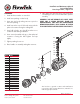
4
3
4
6
2
1
14
11B
15
18
19
26
26
25
29
28
23
24
11A
12
10
5
Item Name
1 Body
2 End Cap
3 Ball
4 Seat*
5 Stem
6 Body Seal*
7 Anti-Static Device
8 Thrust Bearing*
9 Thrust Washer*
10 Stem Packing*
11 Packing Gland
12 Belleville Washer
13 Tab Lock Washer
14 Stop Set Sleeve
15 Stop Bolt
16 Handle
17 Nut
18 Handle Sleeve
19 Locking Device
*Parts included in the repair kits
This brochure is general in nature and manufacturer
reserves the right to change dimensions, materials or to
make design improvements