
Accessories Owner manual


All information herein is proprietary and condential and may not be copied or reproduced without the expressed written consent of BRAY INTERNATIONAL, Inc.
The technical data herein is for general information only. Product suitability should be based solely upon customer’s detailed knowledge and experience with their application.
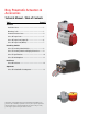
Pneumatic Actuator & Accessories
Installation : 3
All information herein is proprietary and condential and may not be copied or reproduced without the expressed written consent of BRAY INTERNATIONAL, Inc.
The technical data herein is for general information only. Product suitability should be based solely upon customer’s detailed knowledge and experience with their application.
Pneumatic Actuator & Accessories
Installation : 3
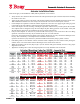
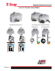
Actuator Installation Notes
These notes apply to the installation of Bray S92/93 pneumatic valve actuators.
• Verify that the valve and the actuator are both in the same position (both open or both closed) before mounting
the actuator to the valve.
• Apply a light coating of grease to the inside of the actuator output bore before installing the actuator on the valve.
This will allow the actuator to be more easily removed from the valve stem even after years of service.
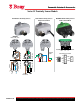
• If stem adapters are required to match the actuator output bore to the valve stem, apply a light coating of grease
to the inside of the stem adapter as well as the inside of the actuator output bore.
• Some stem adapters are kits consisting of multiple components. These kits may contain spacers that look like
stem adapters, but are designed to keep the stem adapter in place during operation of the actuator. Verify that
all stem adapters and spacers are installed in the proper position and sequence.
• If keyed stem adapters are used, the key must be held in the keyway so that it will not work loose during
operation of the actuator. The key may be retained by any one of several methods:
If the valve stem height matches the depth of the actuator output bore, use a key that ts the full length of the
keyway. Tack weld the key to the adapter before installation in the actuator.
Upset the end of the keyway after the key has been installed in the shaft by using a punch or chisel.
• If mounting studs are used instead of bolts, thread the studs completely into the actuator before placing the
actuator on the valve. This assures that the full strength of the connection is achieved.
• While the mounting bolts are only nger tight, cycle the actuator fully open and fully closed to verify proper
alignment on the valve.
• Tighten the mounting bolts or nuts in a diagonal pattern to evenly distribute stress in the bolts.
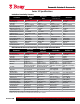
Actuator Mounting Codes for S92/93 - Imperial (In)
Actuator
Sizes
Valve
Code
Inner Bolt Circle Outer Bolt Circle Stem Hole
Bolt Circle
(+/- .005)
No.
Holes
Bolt Size
Bolt Circle
(+/- .005)
No.
Holes
Bolt Size
Bore
Diameter
(+/- .004)
Across
Flats
(+ .002-.0)
Depth
Keyway Width
(+ .002-.0)
48 AA 1.42 4 #10-32 1.97 4 1/4-20 0.4 0.32 1.3 NA
63 A 1.969 4 1/4-20 2.756 4 5/16-18 0.552 0.395 1.38 NA
83 C 1.969 4 1/4-20 2.756 4 5/16-18 0.749 0.513 1.46 NA
93 C 1.969 4 1/4-20 2.756 4 5/16-18 0.749 0.513 1.46 NA
119 E 2.756 4 5/16-18 4.921 4 1/2-13 1.182 0.867 2.2 NA
128 E 2.756 4 5/16-18 4.921 4 1/2-13 1.182 0.867 2.2 NA
160A E NA NA NA 4.921 4 1/2-13 1.182 0.867 2.2 NA
160B F NA NA NA 4.921 4 1/2-13 1.38 NA 2.38 0.394
210 G 4.921 4 1/2-13 6.496 4 5/8-11 1.97 NA 2.76 0.472
255A H 6.496 4 5/8-11 4.724 X 7.874 4 5/8-11 2.505 NA 4.25 0.625
255B K 6.496 4 5/8-11 4.724 X 7.874 4 5/8-11 3.006 NA 4.25 0.750
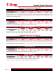
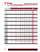
Actuator Mounting Codes for S92/93 - Metric (mm)
Actuator
Sizes
Valve
Code
Inner Bolt Circle Outer Bolt Circle Stem Hole
Bolt Circle
(+/- .127)
No.
Holes
Bolt Size
Bolt Circle
(+/- .127)
No.
Holes
Bolt Size
Bore Dia.
(+/-.102)
Across Flats
(+ .050-.0)
Depth
Keyway
Width
48 AA 36 4 M5 x 0.8P 50 4 M6 x 1.0P 10 8 33 NA
63 A 50 4 M6 x 1.0P 70 4 M8 x 1.25P 14 10 35 NA
83 C 50 4 M6 x 1.0P 70 4 M8 x 1.25P 19 13 37 NA
93 C 50 4 M6 x 1.0P 70 4 M8 x 1.25P 19 13 37 NA
119 E 70 4 M8 x 1.25P 125 4 M12 x 1.75P 30 22 56 NA
128 E 70 4 M8 x 1.25P 125 4 M12 x 1.75P 30 22 56 NA
160A E NA NA NA 125 4 M12 x 1.75P 30 22 56 NA
160B F NA NA NA 125 4 M12 x 1.75P 35 NA 60 10
210 G 125 4 M12 x 1.75-6H 165 4 M20 x 2.5P 50 NA 70 12
255A H 165 4 M20 x 2.5P 120 x 200 4 M20 x 2.5P 64 NA 108 16
255B K 165 4 M20 x 2.5P 120 x 200 4 M20 x 2.5P 76 NA 108 19