
Instruction Manual

Installation and Maintenance Manual
Multiport Threaded and Weld End Ball Valves
Date: May 2011 / Page 3 of 3
®
A Subsidiary of BRAY INTERNATIONAL, Inc.
FLOW-TEK, Inc. Tel: 832.912.2300
© 2011 Flow-Tek, Inc.
8323 N. Eldridge Pkwy #100 Fax: 832.912.2301
Houston, Texas 77041 www.flow-tek.com
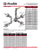
Body Bolt Torque Chart Stem Nut Torque Chart
Size
Torque
(In-Lb)
Bolt Size Size
Torque
(In-Lb)
Nut Size
1/4” 106 1/4” - 20UNC 1/4” 71 M12x1.75
3/8” 106 1/4” - 20UNC 3/8” 71 M12x1.75
1/2” 150 5/16” - 18UNC 1/2” 71 M12x1.75
3/4” 150 5/16” - 18UNC 3/4” 106 M14x2.0
1” 150 5/16” - 18UNC 1” 106 M14x2.0
1 1/4” 195 3/8” - 16UNC 1 1/4” 133 M18x2.5
1 1/2” 195 3/8” - 16UNC 1 1/2” 133 M18x2.5
2” 354 1/2” - 13UNC 2” 168 M22x2.5
2 1/2” 354 1/2” - 13UNC 2 1/2” N/A N/A
3” 354 1/2” - 13UNC 3” N/A N/A
4” 664 5/8” - 11UNC 4” N/A N/A
No. Part Name Material
1 Body ASTM A351 Gr.
CF8M
2 End Cap ASTM A351 Gr.
CF8M
3 Ball SS 316
4 Seat TFM 1600
5 Gasket TFM 1600
6 Stem SS 316
7 Thrust Washer TFM 1600
8 O-Ring Viton
9 Stem Packing TFM 1600
10 Gland SS 304
11 Belleville Washer SS 301
12 Stem Nut SS 304
13 Lock Saddle SS 304
14 Space Washer SS 304
15 Stop Plate SS 304
16 Handle SS 304
17 Handle Sleeve Vinyl
18 Handle Nut SS 304
19 Body Bolt SS 304
20 Pin Insert SS 304
21 Stop Pin SS 304
22 Blank End ASTM A351 Gr.
CF8M
23 Anti-Static Device SS 316
24 End Cap (Inner) ASTM A351 Gr.
CF8M
25 ACP Gasket (Inner) TFM 1600
20
19
9
10
11
12
13
14
16
17
18
15
2
2
5
5
4
1
1
5
2
1
8
7
6
21
22
22
22
22
1
2
5
3
TORQUE DATA
The body bolts of the valve should be tightened evenly. Tighten one-side snugly, then
the one diagonally across. Repeat for the other bolts, bringing them all down tightly
in sequence to the torque shown below.
ASSEMBLY DIAGRAM
Regular Threaded
Female End Cap
Regular Weld Type
End Cap
Inline Weld Type
End Cap