
Instruction Manual


All information herein is proprietary and confidential and may not be copied or reproduced without the expressed written consent of
BRAY INTERNATIONAL, Inc. The technical data herein is for general information only. Product suitability should be based solely upon customer’s
detailed knowledge and experience with their application.
S98 O & M : 7
Series 98 Operation & Maintenance
Ensure the valve and actuator are aligned to the same
position (i.e., valve closed - actuator closed or both in
open). For spring return actuators, align the valve to the fail
safe position of the actuator. If a sandwich gearbox manual
override is used, then also make sure it is aligned with the
valve and actuator position.
Secure the valve, bolt the mounting bracket to the valve and
kit). Position the actuator to align the valve stem (or coupler
shaft) with the yoke bore and slide the actuator on until the
actuator seats on the bracket mounting surface (or on the
When using a manual override sandwich gearbox between
the valve following the gearbox installation procedure. Back
off the gearbox travel stop bolts. Mount the actuator on the
gearbox with the coupler shaft and bolt up the actuator on
In order to align the bolt holes, it may be necessary to loosen
the valve-bracket bolting slightly. The actuator mounting
bolts should easily thread into the actuator base without side
turn the actuator a bit and/or adjust the actuator travel stops.
as the case may be.
Before operating the actuator, declutch the manual override,
if present. The travel stops of the actuator shall limit the
stroke and not those on the gearbox/valve, if present.
Adjust the travel stop bolts of the actuator for the proper
open and closed valve positions, per valve manufacturer’s
page 24 for the travel adjustment range for different models.
Tighten the travel stop bolts lock nuts after adjusting the
stop bolts. Ensure the travel stops on gearbox or valve, if
provided, are now adjusted and locked to fractionally lag the
actuator’s stop position.
Ensure the manual overrides are de-clutched or fully retracted
before putting the actuator to test in power operation mode.
Pneumatically stroke the actuator several times to check
proper and smooth operation. If the actuator is equipped with
a switchbox or other accessories, adjust them at this time.
NOTICE
It is recommended to ground the actuator assembly against static
electricity..
4.0 Operation Guidelines
Series 98 actuators operate well in both on-off and modulating
applications. The accessories, control elements, tubing and
performance of the actuator.
Maximum Operating Pressure (MOP) of the actuator is
mentioned on the nameplate and shall not be exceeded. Suitable
pressure regulator and safety valve shall be incorporated in the
supply line, if the line pressure is higher than this.
CAUTION
Do not pressurize from the cap end port of the spring return
actuator. This port is normally fitted with a breather filter. If there
is a possibility of the actuator being submerged temporarily in
water due to flooding, then this port must be provided with an
extension pipe with the breather filter on the pipe end, at a safe
height above the water level.
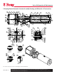
Spring Return actuators work on air stroke or spring stroke by
pressurizing or venting respectively, the adaptor side port (rod
end side). A 3/2 way valve is typically used.
DA models require alternate ports to be pressurized and vented
for stroking. A 5/2 way direction control valve or two 3/2 way
valves may be used.
DD models have adaptor ports of the cylinders tubed in parallel
with the end cap ports of the other side cylinder. The two
cylinders work simultaneously with cap end of one and rod end
of the other pressurized, at a time.