
Instruction Manual

All information herein is proprietary and confidential and may not be copied or reproduced without the expressed written consent of
BRAY INTERNATIONAL, Inc. The technical data herein is for general information only. Product suitability should be based solely upon customer’s
detailed knowledge and experience with their application.
S98 O & M : 26
Series 98 Operation & Maintenance
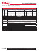
14.0 Series 98 General Specifications
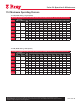
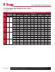
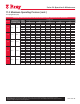
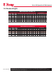
GENERAL SPECIFICATIONS
RANGE
Model
ISO
Mounting
Base
Rated Torque
Spring End Torque
Nm
Largest
Cylinder Size
MOP
DA- Symm
Maximum
Stem Acceptance
Diameter
Maximum
Stem Height
Over Travel
(on either side)
Nm Lb-in Min Max inch psi mm inch mm ± degrees
45 E2 F12/F16 4,500 39,830 1,070 2,675 14 59 50.0 1.97 183 5
73 E2 F12/F16 7,30 0 64,612 2,130 4,280 16 60 63.5 2.50 216 5
14 E3 F16/F25 14,000 123,914 3,485 7,845 20 62 76.2 3.00 240 5
24 E3 F25/F30 24,000 212,424 6,555 15,150 24 55 114.3 4.50 295 3
45 E3 F30/F35 45,000 398,295 11,950 25,595 28 62 152.4 6.00 318 3
CONFIGURATIONS
DA Double Acting- Single Cylinder
DD Double Acting- Dual Cylinders
SC Spring Return- Fail CW
SO Spring Return- Fail CCW
OPERATING CONDITIONS
Pressure Range 40 - 150 psi
Media Dry Compressed Air / Natural Gas Contact factory for other media
Temperature Range -
Standard Options
Standard : -20°F to 200°F (-29°C to 93°C)
High Temp : Up to 300°F (149°C)
Contact factory for extended ranges
Low Temp : Down to -50°F (-46°C)
COMPLIANCES
Torque Base Mounting dimensions options per ISO 5211: 2001(E) or MSS SP-101-1989
Accessories Shaft Driven Accessories Mounting as per NAMUR-VDE
Testing In accordance with EN 15714-3:2009
Ingress Protection IP66/IP67M per IEC 60529
Safety ATEX, SIL 3