
Instruction Manual

All information herein is proprietary and confidential and may not be copied or reproduced without the expressed written consent of
BRAY INTERNATIONAL, Inc. The technical data herein is for general information only. Product suitability should be based solely upon customer’s
detailed knowledge and experience with their application.
S98 O & M : 13
Series 98 Operation & Maintenance
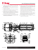
6.5 Torque Module
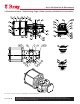
6.5.1 Disassembling the Torque Module
NOTICE
Either the Spring Module or the Pressure Module must be
removed from the Torque Module to allow for removal of the
Guide Bar and Yoke Assembly from the Torque Module.
Disconnect the Piston Rod (35) and the Spring Rod (34)
from the Guide Block prior to disassembly.
Remove the position Indicator (29), if provided.
Take off the Accessory Drive Shaft Assembly (11) from top
of the Yoke.
Remove the Housing Cover Bolts (12) and Lock Washers (13).
Tighten the two Set Screws (14) on the Housing Cover
(3), half turn at a time alternately till the Housing Cover is
separated enough to pry off the Housing with a blunt tool.
Gently tap with plastic hammer or pull off the Guide Bar (2)
from the Guide Block (25) and the Housing (1).
Rotate and center the Yoke Assembly, move the Guide
Block towards the Yoke center and lift the Yoke Assembly
out of Housing.
NOTICE
For smaller models (up to 14E3) this can be done by hand.
Larger models may require use of a hoist to support the weight
of the Yoke Sub assembly. For this, remove the Screw (17) off
the Yoke and fit an eye bolt in place.
Secure the Yoke Assembly and remove the Retainer Plate
Screws (28) and the Retainer Plate (24).
Pull out the Yoke Pin (23), and the upper Slider Block (22).
Slide the Guide Block out of the Yoke (21) and remove the
bottom Slider Block.
Remove the Yoke sealing O-rings (5) from the Housing and
Housing Cover, if replacement is required.
The Yoke Bearings (4) in the Housing and the Housing
only be removed for replacement with suitable tools.
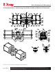
6.5.2 Service & Reassembly of the Torque Module
Replace the DU bushings in the Housing, the Housing Cover
and the Guide Block.
Screws (28), applying a drop of thread lock compound on
the screw threads.
Flip the Yoke over, grease the bottom slot and the Slider
Block (22) generously and slide the Slider Block into the
slot.
Grease the Guide Block bushings and slide the Guide Block
between the arms of the Yoke aligning the Yoke Pin bushings
with the lower Slider Block pin hole.
Grease the Yoke Pin (23) and slide it through the upper slot
in the Yoke and the Guide Block pin bearings, locating it
in the lower Slider Block hole. Push the Yoke Pin down to
touch the bottom Retainer Plate.
Grease the upper slot and the Slider Block and slide it down
on the Yoke Pin through the upper slot till it rests on the
Guide Block.
Fit the upper Retainer Plate to complete the Yoke Assembly.
Lubricate and Install the Yoke O-ring (5) in the Housing
and grease the bearing in the Housing and the Yoke seating
raised face.
Carefully slide in the Yoke Assembly into the Housing
bearing and push it down to seat it on the raised seating face
in the Housing.
Grease and slide in the Guide Bar (2) through the Housing
and Guide Block.
top of the Yoke, applying a drop of thread lock compound.
Grease the upper journal of the Yoke.
in the Housing Cover and locate it on the Yoke upper journal
Bolts (12). Ensure the set screws on the Housing Cover are
backed off fully.
Locate the Accessory Drive Shaft Assembly on the top of
the Yoke, and set the screw on Yoke into the slot in the plate.
Plate Bolts. Fit the indicator on the drive shaft.
Thread the travel Stop Bolts with the Lock Nuts into the
Torque Module Housing