
Instruction Manual

All information herein is proprietary and confidential and may not be copied or reproduced without the expressed written consent of
BRAY INTERNATIONAL, Inc. The technical data herein is for general information only. Product suitability should be based solely upon customer’s
detailed knowledge and experience with their application.
S98 O & M : 11
Series 98 Operation & Maintenance
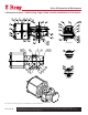
Sling and support the Spring Module and remove the
Module. Pull off the module carefully so as not to damage
the threads on the Spring Rod and the Adaptor Plate Studs.
6.3.2 Service & Reassembly of the Spring Module
from the cover end.
the Spring Rod and slide it back in.
Install the Retainer Ring back in the Spring Rod groove.
Fit End Cover back with new O-ring (59).
6.4 Pressure Module
CAUTION
Ensure the ports are vented to atmosphere before disassembly
of Pressure Module. Failure to do so could cause severe injury.
To take the Pressure Module off the Spring Return Actuator,
first the Spring Module must be removed or at least the Spring
Rod must be disconnected from the Guide Block (steps 1-3), as
described in section 6.3.1.
If the actuator is provided with a Jackscrew or Extended Travel
Stop on the Pressure Module, first ensure to back them off fully
and remove them from the Pressure Module by unfastening the
bolts holding the assembly on the End Cap.
6.4.1 Removing the Pressure Module from
Actuator
Use an extended socket or tube spanner and unscrew the
Piston Rod (35) from the Guide Block (25) in Torque
Module.
Sling and support the Pressure Module. Remove the Adaptor
now be pulled off the Torque Module. Pull off the module
carefully so as not to damage the threads on the Piston Rod
and on the Adaptor Plate Studs.
groove.
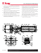
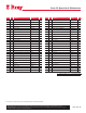
6.4.2 Disassembling the Pressure Module
Secure the Module and unscrew the Tie Rod Nuts (40).
Gently tap the End Plate (34) off the cylinder Barrel (32)
with a plastic mallet and remove the End Plate.
Slide the Cylinder Barrel over and off the Adaptor Plate
(31) and Piston (33), being careful not to scratch or dent the
honed and chrome plated surface of the barrel.
Take the Piston Assembly off the Adaptor Plate, taking care
not to damage the threads.
Tie Rods (39) may be unscrewed from the Adaptor Plate.
Remove the Retainer Ring (45) and take the Split Collars (38)
off the Piston Rod (35) upper groove. Pull the Piston Rod
off the Piston and remove the Split Collars from the lower
groove.
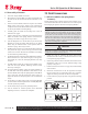
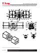
6.4.3 Service & Reassembly of the Pressure
Module
NOTICE
The wear parts (all seals, piston wear bands and rod guide
bushings in the Repair Kit) shall be replaced during the
maintenance cycle. Ensure the replacement seals are suitable
for the service temperature
The assembly of the Pressure Module is done in vertical
orientation.
Use Dow Corning Molykote 55 lubricant in the Pressure Module.
To reassemble, secure the Adaptor Plate horizontally, after
below, to accommodate the Piston Rod. The rod seal groove
side of the Adaptor faces upwards.
groove in Adaptor Plate with the seal lip towards piston side.
Lubricate and install the Adaptor O-ring (44).
Lubricate the piston rod O-ring (41) and install in the groove
on the piston rod.
Grease and slip in the Split Collars on the Piston Rod lower
groove and slide in the Piston Rod (hex side) through the
Piston till the split collars locate in the counter bore in the
piston.
Install the Split Collars on the upper groove similarly and
secure it by the Spiral Retainer Ring.
Lubricate the Piston Rod and carefully slide in the Piston
Assembly through the Rod Seal and Guide Bushing in the
Adaptor Plate. Beware of the pinch points between the
Piston and the Adaptor plate while lowering the Piston
Assembly on the Adaptor Plate inner face.
Lubricate and install the Wear Bands (42) and the Piston
Quad Seal (43) on the Piston.