SERIES 98 PNEUMATIC SCOTCH YOKE ACTUATOR OPERATION AND MAINTENANCE MANUAL
Series 98 Operation & Maintenance Contents 1.0 Safety Information - Definition of Terms. . . . . . . . . . . . . . . . . . . . . . . . . . . . . . . . . . . . . . . . . . . . . . . . . . . . . . . . . . . . . . . . 5 1.1 Hazard-free use . . . . . . . . . . . . . . . . . . . . . . . . . . . . . . . . . . . . . . . . . . . . . . . . . . . . . . . . . . . . . . . . . . . . . . . . . . . . . . . . . . . . . . . . 5 1.2 Qualified Personnel . . . . . . . . . . . . . . . . . . . . . . . . . . . . . . . . . . . .
Series 98 Operation & Maintenance 15.1.1 Installing Hydraulic Override on Spring Return Actuators . . . . . . . . . . . . . . . . . . . . . . . . . . . . . . . . . . . . . . . . . . . . . . . . . 27 15.1.2 Operation - Spring Return Hydraulic Override . . . . . . . . . . . . . . . . . . . . . . . . . . . . . . . . . . . . . . . . . . . . . . . . . . . . . . . . . .28 15.2 Installing Hydraulic Override on DA Actuator . . . . . . . . . . . . . . . . . . . . . . . . . . . . . . . . . . . . . . . . . . . . . . .
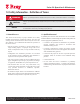
Series 98 Operation & Maintenance 1.0 Safety Information - Definition of Terms WARNING CAUTION NOTICE indicates a potentially hazardous situation which, if not avoided, could result in death or serious injury. indicates a potentially hazardous situation which, if not avoided, may result in minor or moderate injury. used without the safety alert symbol indicates a potential situation which, if not avoided, may result in an undesirable result or state, including property damage. 1.
Series 98 Operation & Maintenance 2.0 Introduction 3.0 Installation The instructions and guidelines in this manual enable competent technicians to install, operate, adjust and carry out routine maintenance activities on Series 98 pneumatic actuators. Responsibility lies with the user to follow the instructions in this and in any additional documentation related to the product and accessories supplied with it.
Series 98 Operation & Maintenance Ensure the valve and actuator are aligned to the same position (i.e., valve closed - actuator closed or both in open). For spring return actuators, align the valve to the fail safe position of the actuator. If a sandwich gearbox manual override is used, then also make sure it is aligned with the valve and actuator position. 4.0 Operation Guidelines Secure the valve, bolt the mounting bracket to the valve and performance of the actuator. kit).
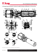
DIVISION THIRD ANGLE BTSI CUSTOMER DRAWING NO. ERN 151127 PRIMARY UNITS ES-00019 SHEET RELEASED MM R REV. 1 OF 2 00 Series 98GENERAL Operation & 98, Maintenance ASSEMBLY, SERIES SPRING RETURN PNUEMATIC ACTUATOR IOM/MANUALS 5.
Series 98 Operation & Maintenance ITEM DESCRIPTION MATERIAL QTY. 1 Yoke Housing Ductile Iron 1 2 Guide Rod Alloy Steel 1 3 ITEM DESCRIPTION MATERIAL QTY.
Series 98 Operation & Maintenance 6.0 Maintenance Series 98 actuators are designed for long service periods between maintenance, in demanding conditions. However, a preventative maintenance program is essential for ensuring good performance, safe operation, extended life of equipment and to avoid expensive down time. The service conditions, load and cycling frequency may vary largely, which would require the maintenance program to be suitably designed, with sound judgment of the working conditions.
Series 98 Operation & Maintenance Sling and support the Spring Module and remove the Slide the Cylinder Barrel over and off the Adaptor Plate (31) and Piston (33), being careful not to scratch or dent the honed and chrome plated surface of the barrel. Module. Pull off the module carefully so as not to damage the threads on the Spring Rod and the Adaptor Plate Studs. 6.3.
Series 98 Operation & Maintenance Apply 10-15 psi air pressure to ports alternately to check for smooth stroking for 5-10 cycles and then raise to 80 psi and hold the pressure to check for any leaks past the Piston, through the Rod Seal and the Barrel O-rings. Carefully lift and slide in the Barrel over the Piston Wear Bands, Quad Seal and Adaptor O-ring and push it down on to the Adaptor Plate. Thread the Tie Rods into the Adaptor Plate, use thread lock compound on the threads.
Series 98 Operation & Maintenance 6.5 Torque Module 6.5.2 Service & Reassembly of the Torque Module 6.5.1 Disassembling the Torque Module NOTICE Either the Spring Module or the Pressure Module must be removed from the Torque Module to allow for removal of the Guide Bar and Yoke Assembly from the Torque Module. Disconnect the Piston Rod (35) and the Spring Rod (34) from the Guide Block prior to disassembly. Remove the position Indicator (29), if provided.
Series 98 Operation & Maintenance 6.6 Reassembly of Actuator Secure the Torque Module on its base. Back off the travel Stop Bolts (19) fully and manually turn the Yoke to one side on which the Pressure Module is to be Lift the Pressure Module, lubricate and place the module 7.0 Field Conversions 7.1 Fail Safe Condition (for Spring Return Actuators) The fail safe direction on Series 98 spring return actuator can be reversed from fail CW to fail CCW and vise versa.
Series 98 Operation & Maintenance NOTICE NOTICE Actuator Designation needs to be suitably changed (from FCW to FCCW or vise versa) on the name plate, after completing this configuration change. Actuator Designation needs to be suitably changed and Maximum Operating Pressure of the actuator to be suitably updated on the name plate, after completing this configuration change. 7.
DIVISION THIRD ANGLE BTSI 151127 MM 32 43 42 33 44 ES-00020 SHEET Series 98 Operation & Maintenance1 OF 2 8.0 Pneumatic Actuator - Double Acting,IOM/MANUALS Single Cylinder Assembly and 44 DRAWING NO.
Series 98 Operation & Maintenance ITEM DESCRIPTION MATERIAL 1 Yoke Housing Ductile Iron 1 27 2 Guide Rod Alloy Steel 1 28 3 QTY. ITEM ** DESCRIPTION MATERIAL QTY.
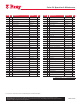
DIVISION CUSTOMER THIRD ANGLE BTSI PRIMARY UNITS ERN DRAWING NO. RELEASED SHEET 151127 ES-00021 Series 98 Operation & Maintenance MM R 1 OF 2 REV. 00 GENERAL ASSEMBLY, SERIES 98, 9.
Series 98 Operation & Maintenance ITEM DESCRIPTION MATERIAL QTY. ITEM 1 Yoke Housing 2 3 Ductile Iron 1 26 Guide Rod Alloy Steel 1 27 Housing Cover Ductile Iron 1 28 4 ** Bushing (Yoke) PTFE Bronze 2 5 * O-Ring (Yoke) Buna-N 2 6 * O-Ring (Cover) Buna-N 1 Top Cover Ductile Iron 1 O-Ring (Top Cover) 7 DESCRIPTION MATERIAL QTY.
Series 98 Operation & Maintenance 10.0 Bolting Torques and Tools PRESSURE MODULE Tie Rod Thread 8 9 10 12 14 16 18 20 22 24 28 M10 M12 M12 M16 M16 M20 M20 M24 M24 M30 M30 Spanner Size, Metric 16 18 18 24 24 30 30 36 36 46 46 Torque, Nm 26 38 47 89 121 197 249 369 446 669 455 End Plug, NPT 1.25 1.5” 1.5” 2” 2” 2” Allen Key .
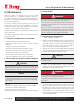
Series 98 Operation & Maintenance 11.0 Maximum Operating Pressure 11.
Series 98 Operation & Maintenance 11.0 Maximum Operating Pressure (cont.) 11.
Series 98 Operation & Maintenance 11.0 Maximum Operating Pressure (cont.) 11.4 Spring Return (Bar) MAXIMUM OPERATING PRESSURE FOR SPRING RETURN ACTUATOR - Symmetrical Yoke / Canted Yoke Model Rated Torq Nm 45 E2 73 E2 14 E3 24 E3 45 E3 4500 7300 14000 24000 45000 Lb-in 39830 64612 123914 212424 398295 Pressure, bar Cyl Size S1 S2 S3 S4 S5 S C S C S C S C P08 10.3 10.3 10.3 10.3 10.3 10.3 P09 10.3 10.3 10.3 10.3 10.3 P10 10.1 8.6 10.3 9.3 10.3 10.3 10.
Series 98 Operation & Maintenance 12.0 Module Weights MODULE WEIGHTS (APPROX), Lbs Model Rated Torq.
E B ØH Series 98 Operation & Maintenance T 13.0 Series 98 Dimensions FRONT VIEW C LEFT VIEW L ØN 12.70 4.0 S 30 20 ØQ R 6.0 J ACCESSORY DRIVE DETAILS M5 P 7.00 U 80.0 STEM BORE DETAIL K M RIGHT VIEW TOP VIEW A D F G E B ØH T FRONT VIEW C LEFT VIEW L SERIES 98 MAX DIMENSIONS, inch ØN Model 45E2 ISO Base S A B 14.8 12.70 C D 14.8 14.2 6.3 12.5 26.2 9.4 9.7 9.4 13.4 16.8 15.8 7.9 6.0 15.8 28.5 12.8 11.8 11.3 16.9 4.
Series 98 Operation & Maintenance 14.0 Series 98 General Specifications GENERAL SPECIFICATIONS RANGE ISO Model Mounting Base Rated Torque Nm Lb-in Spring End Torque Nm Largest Cylinder Size MOP DA- Symm Maximum Stem Acceptance Diameter mm inch Maximum Stem Height Over Travel (on either side) Min Max inch psi mm ± degrees 45 E2 F12/F16 4,500 39,830 1,070 2,675 14 59 50.0 1.97 183 5 73 E2 F12/F16 7,300 64,612 2,130 4,280 16 60 63.5 2.
Series 98 Operation & Maintenance 15.0 Hydraulic Override Hydraulic overrides on S98 actuators provide low effort, high thrust in a compact size for manually operating the actuator. The hydraulic override cylinders are single acting on the SR models and double acting on the DA models of the Actuators. These are available on Models 73E2 through 45E3.
Series 98 Operation & Maintenance 15.2 Installing Hydraulic Override on DA Actuator MOP for SR Hydraulic Overrides Model 73 E2 14 E3 24 E3 45 E3 MOP psi Spring Number 1 2 3 4 1730 2045 2630 2980 bar 119 141 181 205 psi 1445 1660 1930 2460 1. Turn the actuator so that the guide block is at the cover end side of the Torque Module and ensure it stays in this position after disconnecting air pressure and electrical power from actuator. 2.
Series 98 Operation & Maintenance MOP for DA Hydraulic Overrides Model 73 E2 14 E3 24 E3 45 E3 2. Pull the cylinder out of the Spring Module and inspect for leakage from the weep hole near the guide nut at the rod end. Proceed to replace seals if leakage is confirmed or as part of preventive maintenance. 5. Secure the cylinder, loosen and remove the rod end guide nut. 6. Pull the piston assembly out of the cylinder.
Series 98 Operation & Maintenance 15.4.2 Servicing Hydraulic Cylinder 1. Drain the oil from the rod side of the cylinder and pull the barrel with the piston and the piston rod out of the Adaptor side block. 2. Pull the barrel off the piston, remove the old seals and wear band. 3. Inspect the barrel and the piston for any damage or scoring. Replace any damaged parts. 4. Replace the seals, wear rings, guide bushings, o-rings on the adaptor and end caps.
Series 98 Operation & Maintenance 16.0 Jackscrew Override 3. Free the Extension Rod from the Jackscrew assembly, apply a drop of medium strength thread lock compound on the extension rod threads and firmly tighten it into the threading in the Guide Block inside the Torque Module. 4. Coat the extension rod with NLGI2 grease. 5. Lubricate and place the flange O-ring into the groove on the jackscrew assembly flange 6.
Series 98 Operation & Maintenance 8. Install a suitable 3 position manual valve to the pneumatic cylinder’s ports, which will either connect the ports to the air supply or vent them to atmosphere. The ports must be vented when operating the manual override (Refer to Figure C). 5. After completing the manual override stroke, disengage the coupler by pulling out the slide key. Back off the jackscrew completely before restoring automatic operation.
Series 98 Operation & Maintenance 16.2 Installing SR Jackscrew Override 1. Disconnect the air pressure and the electrical power from actuator and ensure the actuator is at its fail safe position. 2. Remove the end cover plate on the Spring module. Retain / replace the cover O-ring. 3. Firmly tighten the mounting studs, supplied in the kit, into the spring module end plate. Use a drop of thread lock compound to retain the studs in the end plate threads. 4.
Series 98 Operation & Maintenance 17.0 Extended Stoppers 4. Extended Stoppers allow adjustment of the actuator rotation angle higher than what the travel stops provided on the Torque Module. Apply medium strength thread lock compound to the threads of the Bolt (4) and thread it into the Guide Block and tighten to lock the Bolt on the Guide Block face. single cylinder double acting actuators and on the Spring Module for the spring return actuators.
Series 98 Operation & Maintenance 17.1.2 Adjusting Extended Stopper Connect air supply to the rod end side port of the pneumatic cylinder, adjust the extended stopper screw to required position, and reverse the actuator direction to stop movement by the extended position. 4IGHTEN THE NUTS WITH SPRING WASHERS REFER TO BOLT TORQUE TABLE FOR THE NUT SIZE 17.2.
Series 98 Operation & Maintenance Reference Drawings Description Drg # (YDRAULIC /VERRIDE !SSEMBLY $! %3 (YDRAULIC /VERRIDE !SSEMBLY 32 %3 *ACKSCREW !SSEMBLY $! $IRECT $RIVE %3 *ACKSCREW !SSEMBLY $! 'EAR $RIVE %3 *ACKSCREW !SSEMBLY 32 $IRECT %3 *ACKSCREW !SSEMBLY 32 'EAR $RIVE %3 3ANDWICH 'EARBOX %3 %XTENDED 3TOPPERS 32 %3 %XTENDED 3TOPPERS $! %3 S98 O & M : 36 All information herein is proprietary and confidential and may not be co
Series 98 Operation & Maintenance Trouble shooting potential problems FAULT POSSIBLE CAUSES RECOMMENDED ACTIONS Erratic Movement Inconsistent supply /dirty operating media/ clogged filters Check media supply pressure and line filters, correct as necessary. Refer to Introduction section in this manual for operating media requirements. Inadequate Lubrication Disassemble and lubricate. Refer to Maintenance section in this manual for lubricant specs. Worn /damaged Parts Disassemble and inspect.
Series 98 Operation & Maintenance POTENTIAL MISUSE PREVENTION MEASURES Use in unintended conditions Refer to Introduction & Installation sections in this manual and supporting product documentation.If in doubt, contact manufacturer. Supply pressure greater than the actuator MOP to compensate for valve problems / incorrect selection. Use of appropriate pressure limiting devices in the supply pressure line to limit the pressure to actuator’s MOP is highly recommended and shall be ensured by the end user.
Series 98 Operation & Maintenance All information herein is proprietary and confidential and may not be copied or reproduced without the expressed written consent of BRAY INTERNATIONAL, Inc. The technical data herein is for general information only. Product suitability should be based solely upon customer’s detailed knowledge and experience with their application.
CONTROLS R A Division of BRAY INTERNATIONAL, Inc. 281/894-5454 FAX 281/894-9499 www.bray.com Bray® is a registered trademark of BRAY INTERNATIONAL, Inc. © 2013 Bray International. All rights reserved.