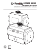
SERIES 92/93 PNEUMATIC ACTUATOR OPERATION AND MAINTENANCE MANUAL
Table of Contents Safety Information - Definition of Terms.............................................................................................. 1 Description of Operation.......................................................................................................................... 2 Operating Medium.................................................................................................................................................. 2 Installation..............................
Series 92-93 Pneumatic Actuator Operations and Maintenance Instructions Safety Information - Definition of Terms ! WARNING indicates a potentially hazardous situation which, if not avoided, could result in death or serious injury. ! CAUTION indicates a potentially hazardous situation which, if not avoided, may result in minor or moderate injury.
Series 92-93 Pneumatic Actuator Operations and Maintenance Instructions Correct and safe operation of this actuator is dependent upon proper transport, storage and installation in addition to proper operation and maintenance. Description of Operation The Flow-Tek Series 92/93 Pneumatic Actuators feature a double piston, rack and pinion mechanism designed to automate quarter-turn valves.
Series 92-93 Pneumatic Actuator Operations and Maintenance Instructions Fail Open Method 1 – Mounting the Actuator Perpendicular to the Pipeline NOTICE Fail Open Method 1 – Mounting the Actuator Perpendicular to the Pipeline – works only with valves that allow the ball to be swung through the seat. Turn the actuator so the long side is perpendicular to the pipeline.
Series 92-93 Pneumatic Actuator Operations and Maintenance Instructions Mounting the Actuator to the Valve The actuator is attached to the valve by means of the mounting kit. Thread the studs into the proper holes in the actuator, before installing the actuator on the valve. The studs should be snug in the bottom of the tapped holes; there is no need to torque them. Install the actuator on the valve or mounting bracket making sure that the base of the actuator fits flat against the mounting flange.
Series 92-93 Pneumatic Actuator Operations and Maintenance Instructions Some valves or operating conditions require that the actuator have more that 5° of travel adjustment. For these conditions, the Series 92/93 actuator can be fitted with extended travel stops in the end caps. (See Pg. 10 for instructions on finding dimensional data) Consult the Flow-Tek distributor in your area for this option.
Series 92-93 Pneumatic Actuator Operations and Maintenance Instructions Troubleshooting Table 1 shows several common symptoms and their remedies.
Series 92-93 Pneumatic Actuator Operations and Maintenance Instructions Final Assembly and Testing NOTICE Three important parameters must be verified before assembly may be continued. 1. The pinion must turn clockwise as the pistons moved toward the center of the body. 2. The 4 mm slot in the top of the pinion must be within a few degrees of perpendicular to the long side of the body. 3. The piston faces must both be the same distance from the end of the body.
Series 92-93 Pneumatic Actuator Operations and Maintenance Instructions ! WARNING Some actuators may have spring cartridges installed. Before disassembly, all spring cartridges must be placed into the relaxed (fully extended) position. All compressed air must be removed from inside the actuator (See warning above) and the actuator pinion must be allowed to rotate so the springs may be relaxed.
Series 92-93 Pneumatic Actuator Operations and Maintenance Instructions Removing Spring Cartridges ! WARNING Before disassembly of the actuator, the pneumatic air supply must be completely disconnected from the actuator, and all compressed air stored within the actuator must be released. Auxiliary devices connected to the actuator, such as tubing, ball valves, solenoid air valves, valve positioners, etc. can block the release of air from within the actuator.
Series 92-93 Pneumatic Actuator Operations and Maintenance Instructions General Pneumatic System Recommendations To maintain maximum efficiency with the Series 92/93 actuator, as well as many other pneumatic devices, the following suggestions are offered: • Air supply lines should be run in accordance with a Standard Piping Practice, and should not have exaggerated loops, which may trap condensate.
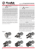
Series 92-93 Pneumatic Actuator Operations and Maintenance Instructions 24 23 19 11 8 9 1 2 20 5 10 13 14 12 15 16 21 6 17 18 4 3 7 22 Figure 3: Series 92/93 exploded-view Item No 1 2 3 4 5 6 7 8 9 10 11 12 Qty. 1 2 1 2 12 max. 1 1 1 1 2 2 2 Description Body Piston Pinion End Cap Spring Cartridge Upper Pinion Bearing Lower Pinion Bearing Retaining Ring Washer, Acetal Bearing Pad, Acetal Guide Ring, Acetal Lock Nut Item No 13 14 15 16 17 18 19 20 21 22 23 24 Qty.
® A Subsidiary of Flow-Tek INTERNATIONAL, Inc. 8323 N. Eldridge Pkwy #100 Houston, Texas 77041 832.912.2300 Fax: 832.912.2301 www.flow-tek.com All statements, technical information, and recommendations in this bulletin are for general use only. Consult Flow-Tek representatives or factory for the specific requirements and material selection for your intended application. The right to change or modify product design or product without prior notice is reserved.