
Manual


5
BRAY Series 70 Servo Pro
Operation and Maintenance Manual
2.2 configuration sWitcHes
NOTICE
DisconnectallelectricpowertotheServoPropriortoadjustingcongurationswitches.Reconnect
electricpoweronlyafterallthecongurationswitchesareintheproperposition.
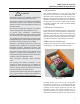
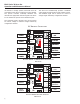
ThecongurationswitchesarelocatedonthetopedgeoftheServoProRevisionF,betweenthe
CalibrationbuttonandtheStatusLED.
CarefullyobservetheONandOFForientationforeachsectionofthecongurationswitcheswhen
selectingdesiredoptions
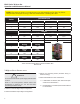
table 1: configuration sWitcH cHart for serVo Pro
reVision f
Switch
Command Signal Input
4-20 mA DC 0-5 VDC * 0-10 VDC 2-10 VDC
1 Off On On On
2 Off Off On On
3 Off Off Off On
FeedbackOutputSignal
4-20 mA DC 0-5 VDC 0-10 VDC 2-10 VDC
4 Off On On N/A
5 On Off Off N/A
6 Off On Off N/A
Forward
Acting
Reverse
Acting
7 Off On
Fail in
Last Position
Fail
Enable **
8 Off On
Fail
Close
Fail
Open
9 Off On
10
Torque
Switch Enable
Torque
Switch Disable
Off On
*TocontroltheServoProwitharemotepotentiometer,settheCommandInputto0-5VDC(seeCommand
SignalNoticesection;page8).
**FailpositionisthepositionthattheServoProwillmovetheactuatorwhenthecontrolsignalisremoved.It
doesnotapplyto0-5VDCor0-10VDCCommandSignals.