
Manual

17
BRAY Series 70 Servo Pro
Operation and Maintenance Manual
5.1.8 control box terminal
The Servo Pro accepts signals from the optional
LocalControlBoxwhichmaybemountedintegrallyor
remotely.
ThewiringtothelocalControlBoxisconnectedatthe
factory and should not requireany adjustmentby the
customer.Ifaeldrepairisrequired,followthewiring
instructions in Section 5.1.8.1.
TheControlBoxhasthefollowingfunctions:
Local / Off / Remote Switch:
Local – The Servo Pro responds to position signals
fromthe localControl Boxand ignores thecommand
signalfromtheremoteprocesscontroller
Off–TheServoProwillnotrespondtopositionsignals
fromeitherthelocalControlBoxorthecommandsignal
fromtheremoteprocesscontroller
Remote – The Servo Pro responds to the command
signalfromtheremoteprocesscontrollerandignores
positionsignalsfromthelocalControlBox.
Open / Stop / Close Switch
Open–theServoPropowerstheactuatormotorinthe
open direction
Stop–theServoProwillstoptheactuatormotor
Close–theServoPropowerstheactuatormotorinthe
closed direction.
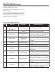
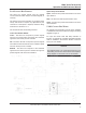
5.1.8.1 control box Wiring
AnoptionallocalControlBoxcanbefactorysupplied,
orinstalledandwiredintheeldaccordingtothewiring
diagraminFigure5.
For open and close travel limit lamp indication to
function,anoptionalsetofauxiliarytravellimitswitches
must be installed in the actuator. Please consult the
factory for more details.
notice
ThediagrambelowisforControlBoxwiringonly;all
otherwiringisnotshown.Pleaserefertothecomplete
wiringdiagramontheinsidecoveroftheactuator.
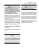
figure 5: samPle Wiring diagram of control box to serVo Pro reVision f WitH an extra set of auxiliary limit
sWitcHes for actuator end of traVel indication