
Manual

16
BRAY Series 70 Servo Pro
Operation and Maintenance Manual
notice
A torque switch that is broken, improperly wired,
or missing from the actuator can result in an open
contactwhichwillbeinterpretedbytheServoProas
theactuatorbeingatitsmaxtorquelimit.
Iftheoptionaltorqueswitchesarenotinstalled,select
TorqueSwitchDisablebysettingCongurationswitch
10toON.
caution
Donotconnectanyhighvoltagepowertothetorque
limitswitchterminalsasdamagecouldresult.
5.1.7 feedback Potentiometer
The Servo Pro uses the signal from the internal
feedback potentiometer to determine the current
actuator position.
Thewiringtothefeedbackpotentiometerisconnected
at the factory and should not require any adjustment
bythecustomer.Ifaeldrepairisrequired,followthe
instructionsbelow:
5.1.7.1 feedback Potentiometer
i
nstallation and calibration
1. Installtheinternalfeedback potentiometer next to
theactuatorindicatorshaftusingthetwothreaded
mountingholesprovided.
2. Thepotentiometerassemblymustbemountedinthe
correctorientationinordertosuccessfullycalibrate
theServoPro.
3. Removetheindicatorrotorfromtheindicatorshaft
sothatthedriveslotonthetopisvisible.
4. Engage the handwheel (pulling it fully outward)
andmanually move theactuatorto the fullyopen
(counterclockwise)position.
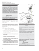
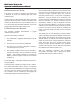
5. Usetheblackfeedbackpotknobtorotatetheblack
feedbackpotcamuntiltheraisedgreenribonthe
potgear(seeFigure4below)isdirectlyin-linewith
theslotonthetopoftheindicatorshaft.
6. Theactuatorisnowreadyforthecalibrationprocedure
describedinSection3.1.
notice
The wiring of the feedback pot is critical to proper
operation.
Connecttheorangewirefromthewiperpinofthepot
tothemiddleterminal.
Connectthegraywirefromthexedpinofthepotthat
isclosesttothewiperpintothe+5Vterminal.
Connectthewhitewirefromthe xedpinofthepot
thatisfarthestfromthewiperpintotheCOMterminal.
Connectavoltmeterbetweenthemiddleterminaland
the COMMON terminal. Apply power to the Servo
Pro,movetheactuatortothefullyopenposition,and
the reading should be close to +5 VDC. Move the
actuatortothefullyclosedposition,andthereading
shouldbecloseto0VDC.
caution
Donotconnectanyhighvoltagepowertothefeedback
potterminalsasdamagecouldresult.
figure 4: feedback Pot mounting and Positioning.
!
!