
Manual

14
BRAY Series 70 Servo Pro
Operation and Maintenance Manual
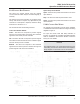
switches1,2and3.RefertothecongurationSwitch
ChartinSection2.2.
Thepotentiometercommandsignaloptionisusefulto
demonstrateanactuatorequippedwithaServoProwhen
a4-20mADCcalibrationdeviceisunavailable.
caution
Donotconnectanyhighvoltagepowertothecommand
signalinputterminalsasdamagecouldresult.
notice
Shielding
Signal/communicationlinesshouldbeshielded.Shield
mustbegroundedatoneendonly,preferablyatthe
controller. Grounding the shield at more than one
locationcanintroducenoiseinthecircuitrybyforming
groundloops.
ThecommandsignalsuppliedtotheServoPromust
beisolatedfromallotherexternalcircuits.
5.1.3 outPut signal terminals
TheServoProsuppliesanoutputsignalthatrepresents
thecurrentpositionoftheactuator.Thecustomerwires
theoutputsignaltoaninputoftheirprocesscontroller.
Theoutputsignalhaspolaritythatmustbeobserved.
Connectthepositiveconductoroftheoutputsignaltothe
OUTPUT(+)terminal.Connectthenegativeconductorof
theoutputsignaltotheOUTPUT(-)RETURNterminal.
Theoutputsignalhasfourdifferentranges selectable
throughcongurationswitches.Theavailablerangesare:
4-20mADC
0-5VDC
0-10VDC
TheoutputsignalissometimescalledtheRetransmission
signal,orpositionfeedbacksignal.
Theoutputsignaliscalibratedbythemicroprocessorat
thesametimethecommandsignaliscalibrated.
caution
Donotconnectanyhighvoltagepowertotheoutput
signalterminalsasdamagecouldresult.
The Servo Proprovides anactive (powered)output
signal.Donot apply any additionalpower source to
thiscircuit.
notice
TheoutputsignalsuppliedbytheServoProisdesigned
todriveanimpedanceofapproximately250Ω,upto
amaximumof500Ω.
The output signal should be isolated from all other
externalcircuits.
Theprocesscontrollerreceivingtheoutputsignalshould
beadjustedtoallowfora+/-2%variance.
ThereisnochangeintheoutputsignalrangeifReverse
Acting mode is selected. The output signal always
operatesinForwardActingmode.
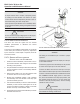
5.1.4 HandWHeel sWitcH terminals
TheServoPromonitorsthepositionoftheactuatormanual
overridehandwheelthroughswitchesconnectedtothe
handwheelterminals.
The wiring to the handwheel terminals is connected
atthefactoryandshouldnotrequireanyadjustmentby
thecustomer.
notice
If the actuator handwheel is engaged (pulled fully
outward) the Servo Pro cannot power the actuator
motorineitherdirection.
Theactuatorhandwheelmustbedisengaged(pushed
fullyinward)fortheServoProtopowertheactuatormotor.
!
!