
Manual

13
BRAY Series 70 Servo Pro
Operation and Maintenance Manual
5.0 HardWare descriPtion
Themicroprocessor-controlledServoProenhancesthe
operationoftheS70actuatorbyprovidingfullpositioning
control,supplyinganactuatorpositionfeedbacksignal,
respondingtovariousswitchinputconditions,performing
self-diagnosticsandindicatingoperationalstatus.
TheServoPromicroprocessoreliminates theneedto
adjustpotentiometers during calibration. Calibration is
performedbysimplypressingabutton.TheServoPro
will automatically seek the fullyclosed andfully open
travellimitsandstorethevaluesinnon-volatilememory.
5.1 terminal block connections
notice
TheServoProwillacceptwiresizesrangingfrom14
to24AWG.
18AWGwireisrecommended.
Largerwirethan14AWGcoulddamagetheterminal
blockconnectionsandshouldnotbeused.
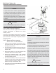
Each terminal connection on the Servo Pro is clearly
labeledonthetopsilkscreentosimplifywiringasshown
inFigures2and3.
5.1.1 PoWer inPut terminals
TheelectricpowersuppliedtotheServoProdrivesthe
actuatormotor,allthecircuitryinsidethemodule,plus
allthedevicesconnectedtothemodulesuchasthelimit
switches,torqueswitches,handwheelswitch,controlbox,
outputsignalandanti-condensationheater.
notice
The electric power supplied to the Servo Pro must
matchtheratingshownontheServoPronameplate.
Eachdifferentrating(100VAC,220VACor24VAC)
requiresadifferentServoProunit.
The Servo Pro must be installed in an actuator that
matchestheratingshownontheServoProname-plate.
Forinstance,a110VACServoPromustbeinstalledin
a110VACactuator.
caution
The terminal block connections designed for high
voltageareplacedbehindasolidlinelabeledHIGH
VOLTAGE on the silk screen. Dangerous high
voltage(110VACorhigher)canbepresentonanyof
theseconductorswhentheServoProisoperating.
Usecautiontoavoidinjurytopersonnelordamage
toequipment.
Donotconnectany110VACor220VACconductorsto
anyterminalblocksoutsidethislabeledarea.
TheServoProisdesignedtoacceptasinglephaseAC
linevoltageofthepropervalue.
The Live conductor should be connected to the Live
terminal.The Neutral conductor should be connected
totheNeutralterminal.
5.1.2 command signal inPut terminals
Applythecommandsignalinput
notice
Note: Ensure that your controller is able to provide
the proper command signal range given the
following input impedance values:
4-20mA 200Ohm
0-5VDC >10MOhm
0-10VDC >10MOhm
The Servo Pro accepts a command signal from the
processcontrollerthatrepresentsthedesiredposition
oftheactuator.Thecustomerwiresthecommandsignal
toanoutputfromtheirprocesscontroller.
Thecommandsignalhaspolaritythatmustbeobserved.
Connectthepositiveconductorofthecommandsignalto
theINPUT(+)terminal.Connectthenegativeconductor
ofthecommandsignaltotheINPUT(-)terminal.
Thecommandsignalhasfourdifferentrangesselectable
throughcongurationswitches.
A potentiometer 10k ohm (or larger) can be used to
generateacommandsignal.Wireonexedterminalof
thepottotheterminallabeled+5Volts.Wirethewiperof
thepottotheterminallabeledINPUT(+).Wiretheother
xedterminalofthepottotheterminallabeledINPUT(-).
Setthecommandsignalto0-5VDCusingConguration
!