
Manual

9
BRAY Series 70 Servo Pro
Operation and Maintenance Manual
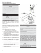
E.Verify(oradjust)thetravelstoplimitsintheactuator
a. Brayactuatorsareshippedwiththetravelswitches
inthefactorydefaultposition-closetravellimit
setat0degreesandtheopentravellimitsetat
90degrees
b. Bray actuators equipped with Servo Pro have
the internal feedback potentiometer set in the
properpositiontomatchthetravelswitchfactory
default(fullycloseat0degreesandfullyopenat
90degrees)
c. Ifthetravelswitchsettingsaremovedfromthe
factory default position, the internal feedback
potentiometermustbeadjustedtomatchthenew
travelswitchsetting.Thisisdonebyperforming
acalibrationroutine.
d. For more details on setting the travel switch
settings, refer to the S70 Operation and
Maintenance Manual.
F. SelecttheTorqueSwitchEnableorDisable
a. If optional torque switches are installed in the
actuator, select Torque Switch Enable. The
optionaltorqueswitchesmustbeproperlysetand
wiredtotheServoPro.RefertotheS70Operation
and Maintenance Manual for more information.
b. Ifoptionaltorqueswitchesarenotinstalledinthe
actuator,selectTorqueSwitchDisable.
Warning
Before applying the appropriate electrical supply
voltage,verifythattheactuatorandServoProhavebeen
properlywiredtothefactorysuppliedwiringdiagram.
NOTICE
Topreventnoisecouplingbetweenconductors,power
lines and signal/communication lines should not be
routedtogetherinthesameconduitorcabletray. If
theymustcrosseachother,thenitshouldonlybedone
atrightangles
Recommendeddistancesbelowshouldbemaintained
betweenpowerandsignal/communicationconduit:
Metal Conduit:
Conductorcarryinglessthan20A=Atleast4in.
Conductorcarryingmorethan20Aupto100kVA=At
least 8 in.
Conductorcarryingmorethan100kVA=Atleast1.5ft
Non-Metallic Conduit:
Conductorcarryinglessthan20A=Atleast8in
Conductorcarryingmorethan20Aupto100kVA=At
least 2 ft
Conductorcarryingmorethan100kVA=Atleast3ft.
Please refer to NEC guidelines for proper wiring
techniquesinUSA.Othercountriesmustfollowalllocal
codesforsafetyrequirements.
Shielding
Signal/communicationlinesshouldbeshielded.Shield
must be grounded at one end only, preferably at the
controller.Groundingtheshieldatmorethanonelocation
canintroducenoiseinthecircuitrybyformingground
loops.
G. Applythecommandsignalinput
notice
Ensure that your controller is able to provide the
proper command signal range given the following
input impedance values:
4-20mA 200Ohm
0-5VDC >10MOhm
0-10VDC >10MOhm
a. Thecommandsignalmustbeconnectedtothe
properterminals.Refertothewiringdiagram.
b. Thecommandsignalinputmustmatchtherange
selectedwiththecongurationswitches.
c. Thecommandsignalmustbeavalidvalue(i.e.,
if4-20mADCisselected,thevaluemustbeno
lessthan4mAandnogreaterthan20mA.)
d. Note:agoodvaluetoselectforCalibrationwould
bemid-travel(i.e.12mADC)
Isolation Transformers
For circuits that are located in the proximity of
excessive electrical noise generators, isolation
transformers should beused to lter and prevent
noisefromenteringintothecircuitry.
!