
Manual


8
BRAY Series 70 Servo Pro
Operation and Maintenance Manual
Switch
Command Input
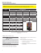
4-20 mA DC 0-5 VDC 0-10 VDC 2-10 VDC
1 On Off Off Off
2 Off Off On On
3 Off Off Off On
10 Off On On On
Output
4-20 mA DC 0-5 VDC 0-10 VDC 2-10 VDC
4 On Off Off N/A
5 Off On On N/A
6 Off On On N/A
Forward
Acting
Reverse
Acting
7 Off On
Fail in
Last
Fail
Enable
8 Off On
Fail
Close
Fail
Open
9 Off On
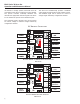
table 2: configuration sWitcH cHart for serVo Pro
reVision d
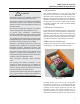
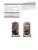
3.0 Quick setuP instructions
Warning
Donotconnecttheelectricpowersupplyuntilinstructed
to do so.
Refer to the Configuration Switch charts and
descriptions in Sections 2.1, 2.2 and 2.3 when
performingtheQuickSetup.
A. SettheCommandSignalInputconguration.
B. SettheFeedbackOutputSignalconguration.
C.Select the Operating Mode (Forward Acting or
ReverseActing)
D. SelectFailEnableorFailinLastPosition
a. IfFailEnableisselected,thenselectFailOpen
orFailClosewithSwitch9
b. IfFailEnableisnotselected,theactuatorwillFail
inLastPosition
!
NOTE: The following chart is for conguration of an older model Servo Pro (Rev. D). Please
verify that the model you are using is the same model before consulting this chart.