S70 DeviceNet Servo Installation & Maintenance Manual Version 11 BRAY CONTROLS 13333 Westland East Blvd.
S70 DeviceNet Servo Installation & Maintenance Manual 1. INTRODUCTION............................................................................................................................... 2 2. HARDWARE DESCRIPTION .......................................................................................................... 3 2.1 HARDWARE FEATURES................................................................................................................ 4 2.2 CONNECTOR WIRING ..................
S70 DeviceNet Servo Installation & Maintenance Manual 1. Introduction The Bray S70 DeviceNet Servo is an ODVA (Open DeviceNet Vendor Association) certified DeviceNet product that provides complete control and monitoring of the Bray S70 Electric Valve Actuator. The basic function of the S70 DeviceNet Servo is to position the S70 Actuator in response to commands from the process controller.
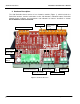
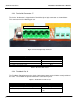
S70 DeviceNet Servo Installation & Maintenance Manual 2. Hardware Description The S70 DeviceNet Servo consists of an electronics module (Figure 1), which includes the DeviceNet interface, terminal connections to the S70 Actuator, calibration button, DeviceNet Network Status Indicator, and connections and indicators to features described in Section Error! Reference source not found..
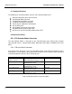
S70 DeviceNet Servo Installation & Maintenance Manual 2.1 Hardware Features The following are standard hardware features of the S70 DeviceNet Servo: DeviceNet 5-position open style connector S70 Actuator Motor connector S70 Actuator Limit Switch connector Feedback Potentiometer connector Red and green calibration LED indicators Green Power LED Green Motor Running Open drive LED Red Motor Running Closed drive LED Bi-color (red / green) DeviceNet Network Status LED 2.2 Connector Wiring 2.2.
S70 DeviceNet Servo Installation & Maintenance Manual 2.2.3 DeviceNet Connector J7 The Series 70 Actuator is shipped with a DeviceNet Open Style connector as shown below: This connector has the following pin-out: V+ CANH SHIELD CANL V- Figure 2: DeviceNet Open Style Connector Description V-, CAN power supply return CAN Low Shield CAN High V+, CAN power supply source Wire Color Black Blue Bare/Gray White Red Table 2: DeviceNet Wire Colors 2.2.
S70 DeviceNet Servo Installation & Maintenance Manual 2.2.5 Calibration Button When the Calibration Button is pressed for 2 seconds, the S70 DeviceNet Servo will start an automatic calibration. 2.3 Normal Operation Since the S70 and the Series 70 Actuator is an integral unit, the S70 is powered from the DeviceNet Bus power. The Actuator motor is powered from the AC line voltage and is controlled by the S70 DeviceNet Servo. The recommended sequence to start the S70 is as follows: 1.
S70 DeviceNet Servo Installation & Maintenance Manual 2.5 Auto Calibration To commence the Auto Calibration, do the following: 1. Press the calibration button for 2 seconds and then release. 2. The S70 will automatically seek the closed position and is indicated by the RED LED D27. If the Actuator is already at the fully closed position, the S70 will move the Actuator open until the Close switch is disengaged, and then move closed until the closed switch engages. 3.
S70 DeviceNet Servo Installation & Maintenance Manual 3. DeviceNet Interface The S70 Servo is an ODVA (Open DeviceNet Vendor Association) compliant product. The ODVA certification ensures that the S70 Servo can operate on any DeviceNet network and supports all of the features required to operate cooperatively on a network with mixed devices which are also ODVA compliant. 3.
S70 DeviceNet Servo Installation & Maintenance Manual The resistor requirements are: 121 ohm 1 % Metal Film 1/4 Watt Terminating resistors should never be included in nodes. Inclusion of this capability could easily lead to a network with improper termination (too high or too low an impedance) potentially causing failure. For example, removal of a node that includes a terminating resistor could result in network failure.
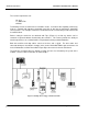
S70 DeviceNet Servo Installation & Maintenance Manual Figure 5: Example of Network connection with tap, Trunk line, and Drop line. Specifications Thick trunk length Thin truck length Max drop length Cummulative drop length 125 Kbps Data Rate 500 m (1640 ft) 100 m (328 ft) 6 m (20 ft) 156 m (512 ft) Table 3: DeviceNet 250 Kbps Data Rate 250 m (820 ft) 100 m (328 ft) 6 m (20 ft) 78 m (256 ft) 500 Kbps Data Rate 100 m (238 ft) 100 m (328 ft) 6 m (20 ft) 39 m (128 ft) Cable Lengths 3.1.
S70 DeviceNet Servo Installation & Maintenance Manual DeviceNet should be grounded at ONE location. Grounding at more then one location may produce ground loops, while not grounding the network will increase sensitivity to ESD and outside noise sources. The single grounding location should be at a power tap. Sealed DeviceNet power taps are designed to accommodate grounding. Grounding near the physical center of the network is also desired.
S70 DeviceNet Servo Installation & Maintenance Manual as a Class 2 circuit. This requires limiting the current in any section to 4 amps. The rating of the system components themselves, however, is 8 amps. The trunk-line can be constructed of either thick cable or thin cable. A combination of both thick and thin cable can be used provided that only one type of cable is used for any section of cable (length between two power taps or between a power tap and the end of the trunk line).
S70 DeviceNet Servo Installation & Maintenance Manual The selection of the power supply should ensure a tolerance of +24 VDC +/- 1% and current capability of 0-16 amps. 3.1.4 Network Status LED This bi–color (green/red) LED (D17, Figure 1) indicates the status of the communication link. Refer to table LED State Off Green Flashing Green Red Flashing Red Table 6: DeviceNet Description The S70 is not on–line and has not completed the Dup MAC_ID test yet. The S70 may also not be powered.
S70 DeviceNet Servo Installation & Maintenance Manual controller has exclusive control of the S70 Servo via the polled message connection. The polled message connection allows the process controller to position the S70 Actuator, and receive the present actuator position. If the process controller establishes an additional Explicit message connection, the process controller could also simultaneously monitor or control other features of the S70 Servo as described in Section (3.1.6). 3.1.
S70 DeviceNet Servo Installation & Maintenance Manual Attribute Description Valve Position Actuator Opened / Closed1 Local / Remote Switch1 Open / Close Limit1 Force Open / Close1 Auto / Manual1 Torque Limit1 Speed Control Enabled Opening Speed Opening Speed Begin Opening Speed End Closing Speed Closing Speed Begin Closing Speed End Failure Mode Enable Failure Position Instant Reverse Delay Serial Number1 Feature Set1 1 Attribute (Hex) 0x64 0x67 Attribute (Decimal) 100 103 0x68 0x69 0x70 0x71 0x72 0x73
S70 DeviceNet Servo Installation & Maintenance Manual When adding devices to a network, it is best to setup an independent workstation with a DeviceNet interface for Node Commissioning. Any Node Commissioning application can be used to configure the S70 Servo. Refer to the application software user manual for specific information on Node Commissioning. 3.3 Communication All communication with the S70 Servo takes place over the DeviceNet network.
S70 DeviceNet Servo Installation & Maintenance Manual Figure 6: An example display of a network created from EDS information When the S70 Servo EDS file is accessed through an application as shown in Figure 7, all of the parameters available for monitoring and configuration are displayed. Since there are more parameters available than can be displayed on the screen at the same time, the parameters can be also displayed in groups. In Figure 8, the Parameter Group “Actuator Status” is displayed.
S70 DeviceNet Servo Installation & Maintenance Manual Figure 7: Display of S70 Parameters supported by the EDS file EDS parameters which are settable can be modified and saved to the S70 Servo. As an example, to change the valve position, the “Valve Position” parameter is highlighted, and then “Modify Parameter” is selected. Figure 9 is an example of an EDS parameter modification display. Once the parameter has been modified, it is saved to the S70 Servo and takes effect immediately.
S70 DeviceNet Servo Installation & Maintenance Manual The S70 Servo supports the following EDS parameters: Valve Position Mac Id Baud Rate Actuator Action Travel Limit Switch Torque Limit Switch Local/Remote/Off Open/Stop/Close Handwheel Speed Control Failure Mode Instant Reverse Delay Serial Number Enabled Features Detailed information on how to use these parameters are provided in the S70 Servo on-line help system.
S70 DeviceNet Servo Installation & Maintenance Manual Figure 8: Example of the Actuator Status EDS Group Display 2000 BRAY CONTROLS Page 20 of 24
S70 DeviceNet Servo Installation & Maintenance Manual Figure 9: Example of setting an EDS parameter 4. Trouble Shooting 4.1 Calibration 1. Verify that the Series 70 CAMS are correctly set (Section 2.4) and are engaged when the Open Limit and Close Limit are reached. 2. Verify that the Feedback Pot (Section 2.2.4), connector J4 is connected and oriented correctly. 3. If the Calibration still fails, ensure that the S70 has been properly wired to the Series 70 Actuator. Review Section 2.
S70 DeviceNet Servo Installation & Maintenance Manual 4.2 Actuator Operation The Series 70 Actuator can be operated in a Remote mode (DeviceNet control) or a Local mode (manual control) if the Series 70 has the switch box option installed. If the Actuator does not operate, depending upon the operating mode, the following are possible causes: If the Series 70 Actuator is operating in the Remote mode, or if the optional switch box is not installed (Remote mode is default), verify the following: 1.
S70 DeviceNet Servo Installation & Maintenance Manual 4.3 DeviceNet Network Errors If the DeviceNet LED D17 ( Figure 1) remains a solid or flashing Red color, then a DeviceNet Refer to the flow chart in Figure 10 as a trouble-shooting guide. network error has occurred.