CONTROLS R OPERATION AND MAINTENANCE MANUAL SERIES 6P Pneumatic Positioner
Safety Instructions - Definition of Terms READ AND FOLLOW THESE INSTRUCTIONS SAVE THESE INSTRUCTIONS ! WARNING indicates a potentially hazardous situation which, if not avoided, could result in death or serious injury. ! CAUTION indicates a potentially hazardous situation which, if not avoided, may result in minor or moderate injury.
CONTROLS R SERIES 6P Pneumatic Positioner Table Of Contents Page Introduction............................................................................................. 4 Product Description. ............................................................................... 4 Manufacturer Warranty........................................................................ 4 Operation Logic. ...................................................................................... 5 Label Description. .......
Bray Series 6P Operation and Maintenance Manual Introduction Manufacturer Warranty Every Series 6P is fully inspected after production to offer the highest quality products. However, we strongly recommend users read this manual carefully to ensure the product is utilized to its fullest potential. Warranty - Bray provides the following warranty regarding products manufactured by it. • This manual should be given to the end-user. • This manual may be changed or revised without any prior notice.
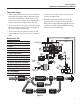
Bray Series 6P Operation and Maintenance Manual Operation Logic • When signal input pressure increases, the bellows (11) pushes the flapper (13), the gap between the nozzle (5) and the flapper (13) increases, which causes pressure in the upper spool chamber (4) to exhaust. This causes the spool (1) to shift right. • As the actuator’s inner pressure increases, the actuator stem (8) rotates.
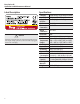
Bray Series 6P Operation and Maintenance Manual Label Description ! NOTICE All Series 6P positioners are supplied as Double Acting. For Single Acting operation, OUT 2 should be plugged with a 1/4” NPT plug. 6 Specifications Category Input Signal Supply Pressure Stroke Air Connection Gauge Connection Protection Cam Ambient Temperature Ranges Linearity Hysteresis Sensitivity Repeatability Air Consumption Flow Capacity Housing Material Weight Double Acting / Single Acting Pneumatic 3-15 psig (0.2 - 1.
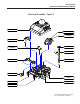
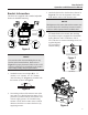
Bray Series 6P Operation and Maintenance Manual Parts and Assembly - Figure 2 COVER *Auto/Manual Adjustment PILOT VALVE SPAN ADJUSTMENT CONNECTOR DOME GEAR CAM INPUT BELLOWS FEEDBACK SHAFT ZERO ADJUSTMENT OUTPUT 1 SIGNAL IN OUTPUT 2 SUPPLY IN *Auto / Manual Adjustment is Factory set, and should not be adjusted.
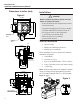
Bray Series 6P Operation and Maintenance Manual Dimensions in Inches (mm) Figure 3 Installation ! 7.34 (186.5) 5.20 (132.1) CAUTION 6.5 (166) 4.8 (122) 2.84 (72.2) When installing a positioner, please read and follow all safety instructions: • Series 6P should be used for quarter-turn valves and actuators only. • All input and supply pressure to valve, actuator, and other related devices must be turned off. • Use a bypass valve or other equipment to avoid entire system shut down.
Bray Series 6P Operation and Maintenance Manual Bracket Information The Series 6P is supplied with a standard adjustable bracket for NAMUR mounting. 3. Attach the Series 6P to the bracket as shown in Figure 8. This sets the alignment of the main shaft and the center of the actuator stem.
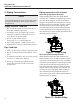
Bray Series 6P Operation and Maintenance Manual 5. Piping Connections NOTICE To avoid introducing moisture or dust, both supply and signal air should be clean, dry, and filtered instrument air. Supply Pressure Condition 1. Dry air with dew point of at least 50°F (10°C) lower than ambient temperature. 2. Avoid dirty or oily air. Filtered air is recommended in compliance with ANSI/ ISA-573 1975 (R1981) instrument grade. 3. Do not use beyond the range of 20-100 psig (1.4 - 7.0 barg) supply air. 4.
Bray Series 6P Operation and Maintenance Manual Adjustment – Cam Adjustment – Span 1. If the valve actuator rotates counter-clockwise to open the valve on increasing air signal, the face of the cam must show “RA (CCW)” (Factory Default). If used on a valve-actuator which rotates clockwise to open the face of the cam must show “DA (CW)” on the face. 2.
Bray Series 6P Operation and Maintenance Manual Adjustment – Poppet Seat Balance Pressure A/M Adjustment NOTICE The Poppet Seat Adjuster is factory set and sealed before the positioner is shipped. Do not adjust Auto / Manual default setting (Automatic) as shown. Poppet Seal Adjuster A/M A/M A/M Automatic/ Manual Hunting occurs • Check if feedback springs (15) have been displaced. • Hunting may occur when the positioner is attached to a very small capacity actuator (ex: Bray Series 92/93 size 48).