
Instruction Manual

All information herein is proprietary and condential and may not be copied or reproduced without the expressed written consent of BRAY INTERNATIONAL, Inc.
The technical data herein is for general information only. Product suitability should be based solely upon customer’s detailed knowledge and experience with their application.
Series 6A Operation & Maintenance – Technical Data
6A O & M : 30
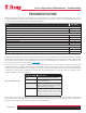
TECHNICAL DATA
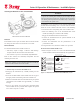
1. Basic Units
3-/4-wire device (terminals 2/4 and
6/8) (6DR52.. and 6DR53..)
• Power supply U
H
18 ... 35 V DC 18 ... 30 V DC
• Current consumption I
H
(U
H
- 7.5 V)/2,4 kΩ [mA]
• Internal capacitance C
i
– 22 nF 22 nF (at "nL")
• Internal inductance L
i
– 0.12 mH 0.12 mH (at "nL")
• For connection to circuits with the
following peak values
– intrinsically safe
U
i
= 30 V DC
I
i
= 100 mA
P
i
= 1 W
at "nA" and "tD":
U
n
= 30 V DC
I
n
= 100 mA
at "nL":
U
i
= 30 V DC
I
i
= 100 mA
Current input I
W
Rated signal range 0/4 ... 20 mA
Load voltage at 20 mA ≤ 0.2 V (corresponds to 10 Ω) ≤ 1 V (corresponds to 50 Ω)
Internal capacitance Ci – 22 nF 22 nF (at "nL")
Internal inductance Li – 0.12 mH 0.12 mH (at "nL")
For connection to circuits with the
following peak values
– intrinsically safe
U
i
= 30 V DC
I
i
= 100 mA
P
i
= 1 W
at "nA" and "tD":
U
n
= 30 V DC
I
n
= 100 mA
at "nL":
U
i
= 30 V DC
I
i
= 100 mA
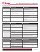
Electrical isolation between U
H
and I
W
between U
H
and I
W
(2 intrinsically safe cir-
cuits)
between U
H
and I
W
Test voltage 840 V DC, (1 s)
Connections
• Electrical Screw terminals 2.5
AWG28-12
Cable gland M20x1.5 or
½-14 NPT
Screw terminals 2.5
AWG28-12
Ex d certified cable gland
M20x1.5, ½-14 NPT or
M25x1.5
Screw terminals 2.5 AWG28-12
Cable gland M20x1.5 or ½-14 NPT
• Pneumatic
Female thread G1/4 EN ISO 228-1 or
¼ -18 NPT
External position sensor (potentiome-
ter or NCS; as option) with the follow-
ing peak values
• U
o
– 5 V
• I
o
(static) – 75 mA
• I
s
(short-time) – 160 mA –
• P
o
– 120 mW
Maximum permissible external
capacitance C
o
– 1 μF
Maximum permissible external
inductance L
o
– 1 mH
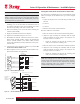
SIPART PS2 Basic device
without Ex protection
Basic device
with Ex d protection
(flameproof enclosure)
Basic device
with Ex ia/ib protection
Basic device
with Ex n/
dust protection
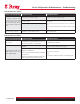
Technical specifications