
Instruction Manual

All information herein is proprietary and condential and may not be copied or reproduced without the expressed written consent of BRAY INTERNATIONAL, Inc.
The technical data herein is for general information only. Product suitability should be based solely upon customer’s detailed knowledge and experience with their application.
Series 6A Operation & Maintenance – Installable Options
6A O & M : 25
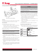
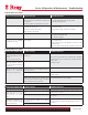
Installing the EMC Filter Module
EMC Module
Function
You will require the EMC lter module if you use an external
position sensor on the positioner, e.g. a potentiometer or a non-
contacting position sensor. The EMC lter module forms the
interface between external position sensors and the motherboard
of the positioner. This module protects the positioner from elec-
tromagnetic effects.
Device features include:
• EMC protection
• Connection to motherboard
• Connecting terminals for an external potentiometer
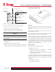
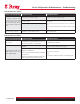
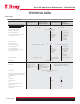
Proceed as follows to install the EMC lter module:
1. Perform Step A to remove the module cover
2. Remove the module cover.
3. Dismantle all existing optional modules.
4. Unscrew the screws of the module rack that are opposite to
the blanking plugs.
5. The EMC lter module has a fastening hole. Tighten the
module on the module rack using the screws provided
6. Lay the ribbon cable of the EMC lter module towards left
through the opening of the module rack.
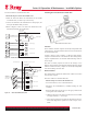
7. Unplug the connector of the internal potentiometer from the
motherboard.
8. Connect the ribbon cable of the EMC module to the
motherboard.
9. Connect the external position sensor to the terminals of the
EMC module.
10. Reinstall the other optional modules in the reverse order.
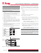
11. Refer to Figures 14 and 15 to reconnect the SIA module in
standard and intrinsically safe applications
12. Install the module cover.