
Instruction Manual

All information herein is proprietary and condential and may not be copied or reproduced without the expressed written consent of BRAY INTERNATIONAL, Inc.
The technical data herein is for general information only. Product suitability should be based solely upon customer’s detailed knowledge and experience with their application.
Series 6A Operation & Maintenance – Calibration & Commissioning
6A O & M : 18
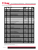
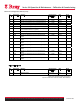
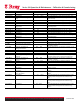
53) FSTI Monitoring Period for
setting the safety seating
0 … 100 (s). Once this set value expires the positioner
switches to its safety position. (Factory defined at 0)
54) FSVL Safety Setpoint
0.0 … 100.0 (%). Default value of the safety position. (Factory
setting is 0%)
55) STNR Station Number
0 … 126 Independent value for each station. (Default position
is 126)
0 Profile Compliant. Can be replaced with other
positioners complying with Profibus PA profile 3.0
56) IDENT Device operating mode
(ID No.)
1 Compliant with Extensions (Factory Defined).
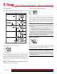
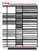
Parameter Function Parameter Values Description
A. PST Partial Stroke Test Used to activate the partial stroke test for cyclic or
manual test of up/down and servo solenoid valves.
A1.STPOS Starting position 0.0 … 100.0 Start position in %. Factory setting is “100.0”
A2.STTOL Starting tolerance 0.1 … 2.0 … 10.0 Start position tolerance in %. Factory setting is
“2.0”
A3.STEP Step height 0.1 ..10.0 ..100.0 Step height of partial stroke test in %
A4.STEPD Step Direction uP / do / uP do Step direction of partial stroke test. Factory setting
is “do”
A5.INTRV Test Interval OFF / 1 … 365 Interval time for cyclic partial stroke in days. “Off”
A6.PSTIN Partial Stroke ref. step time NOINI / (C) ###.# /
Fdini / rEAL
Reference step time for partial stroke in s. “NOINI”
A7.FACT1 Factor 1 0.1 … 1.5 … 100.0 Factor for the formation of limit threshold 1. “1.5”
A8.FACT2 Factor 2 0.1 … 3.0 … 100.0 Factor for the formation of limit threshold 2. “3.0”
A9.FACT3 Factor 3 0.1 … 5.0 … 100.0 Factor for the formation of limit threshold 3. “5.0”
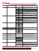
b. DEVI General Control Valve Fault Test for dynamic monitoring of control valve
response.
b1.TIM Time constant Auto / 1 … 400 Defines the attenuation effect of the low-pass filter.
“Auto”
b2.LIMIT Limit 0.1 … 1.0 … 100.0 Sets a base limit in %. “1.0”
b3.FACT1 Factor 1 0.1 … 5.0 … 100.0 Factor for the formation of limit threshold 1. “5.0”
b4.FACT2 Factor 2 0.1 ..10.0..100.0 Factor for the formation of limit threshold 2. “10.0”
b5.FACT3 Factor 3 0.1..15.0..100.0 Factor for the formation of limit threshold 3. “15.0”
C. LEAK Pneumatic leakage Activates the pneumatic leakage test
C1.LIMIT Limit 0.1 .. 30.0 .. 100.0 Sets the limit of the leakage indicator in %. “30.0”
C2.FACT1 Factor 1 0.1 … 1.0 … 100.0 Factor for the formation of limit threshold 1. “1.0”
C3.FACT2 Factor 2 0.1 … 1.5 … 100.0 Factor for the formation of limit threshold 2. “1.5”
C4.FACT3 Factor 3 0.1 … 2.0 … 100.0 Factor for the formation of limit threshold 3. “2.0”
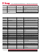
d. STIC Friction (slip-stick effect) Monitors the current static friction of the final
controlling element
d1.LIMIT Limit 0.1 … 1.0 … 100.0 Sets the base limit for the slipstick detection in %.
“1.0”
d2.FACT1 Factor 1 0.1 … 2.0 … 100.0 Factor for the formation of limit threshold 1. “2.0”
d3.FACT2 Factor 2 0.1 … 5.0 … 100.0 Factor for the formation of limit threshold 2. “5.0”
d4.FACT3 Factor 3 0.1 ..10.0..100.0 Factor for the formation of limit threshold 3. “10.0”
E. DEBA Dead zone monitoring Used to measure the automatic adjustment of the
dead zones
e1.LEVEL3 Threshold 0.1 … 2.0 … 10.0 Sets the factor limit threshold to monitor the dead
zone adjustment