
Instruction Manual

All information herein is proprietary and condential and may not be copied or reproduced without the expressed written consent of BRAY INTERNATIONAL, Inc.
The technical data herein is for general information only. Product suitability should be based solely upon customer’s detailed knowledge and experience with their application.
Series 6A Operation & Maintenance – Calibration & Commissioning
6A O & M : 16
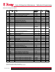
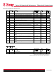
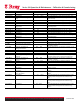
Parameter Function Parameter Values Description
Turn Automatically sets 2) YAGL to 90
◦
WAY Used for linear actuators
LWAY Used for linear actuators
ncSt Used for a non-contacting position sensor on a part
turn actuator
-ncSt Used for a non-contacting position sensor on a part
turn actuator with a reverse direction of action
ncSL Used for linear actuators
1) YFCT Type of position actuator
ncSLL Used for linear actuators
33
◦
2) YAGL Angle of rotation
90
◦
Used for linear actuators
3) YWAY Range of Stroke
Used for linear actuators
4) INITA Initialization (automatic)
NOINI | no/ ###.# | Strt Starts the automatic initialization process
5) INITM Initialization (manual)
NOINI | no/ ###.# | Strt Starts the manual initialization process
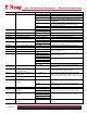
0 MA 0 MA only available for 3 to 4 wire connections.
6) SCUR Current range of setpoint
4 MA Factory setting.
riSE
7) SDIR Setpoint Setup
FALL
Used to reverse the direction of the action of the
setpoint. Factory setting is “rise”
8) SPRA Setpoint split range start
0.0 … 100.0 Used to limit the setpoint. Factory setting is “0”
9) SPRE Setpoint split range end
0.0 … 100.0 Factory setting is “100”
10) TSUP Setpoint ramp OPEN
Auto / 0 … 400
11) TSDO Setpoint ramp CLOSED
0 … 400
Limits the speed of change of the effective setpoint.
Factory setting is “0”
1 – 25
1 – 33
1 – 50
Equal Percentage. Linearizes valve characteristics.
Factory setting is “Lin”
n1 – 25
n1 – 33
n1 – 50
Inverse equal percentage
12) SFCT Setpoint Function
FrEE Freely Adjustable
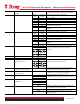
13) SLO
…33) SL20
Setpoint Turning Point
0.0 … 100.0 Assigns a flow metric to each setpoint interpolation
in units of 5%.
34) DEBA Dead Zone of Closed-
Loop Controller
Auto / .1 … 10.0 Adjust the dead zone to the requirements of the
control loop. Factory setting is “Auto”
35) YA Start of the manipulated
variable limit
0.0 … 100.0
36) YE End of the manipulated
variable limit
0.0 … 100.0
Used to limit the mechanical actuator travel from
stop to stop to the configured values. “YE” must
always be larger than “YA”. Factory setting is “100”
MPOS Mechanical position from 0 to 100% between hard
stops.
37) YNRM Manipulated variable
scaling
FLOW Scaling from 0 to 100% over the range between
“YA” and “YE”
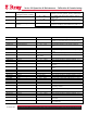
riSE
38) YDIR Direction of Manipulated
Variable
FALL
Used to set the direction of action of the display and
the position feedback Iy. Factory setting is “riSE”
No
uP
Do
39) YCLS Manipulated variable tight
closing
uP do
Used to move the valve into its seat with the
maximum force of the actuator. Factory setting is
“No”
40) YCDO Lower value for tight
closing
0.0 … 0.5 … 100% Factory setting is “0.5”