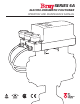
SERIES 6A ELECTRO-pneumatic positioneR OPERATION AND MAINTENANCE MANUAL
Series 6A Operation & Maintenance – Table Of Contents Contents Safety Information - Definition of terms . . . . . . . . 3 Introduction . . . . . . . . . . . . . . . . . . . . . . . . 4 Installation . . . . . . . . . . . . . . . . . . . . . . . . . 5 Field Connections . . . . . . . . . . . . . . . . . . . . . 6 Calibration and Commissioning . . . . . . . . . . . . .11 Factory or Field Installable Options . . . . . .
Series 6A Operation & Maintenance – Safety Safety Information - Definition of terms Q Q WARNING indicates a potentially hazardous situation which, if not avoided, could result in death or serious injury. Caution indicates a potentially hazardous situation which, if not avoided, may result in minor or moderate injury. Notice used without the safety alert symbol indicates a potential situation which, if not avoided, may result in an undesirable result or state, including property damage.
Series 6A Operation & Maintenance – Introduction Introduction The Bray S6A is a microcontroller based positioner for pneumatic actuators. The S6A converts an analog current signal into a valve position pressure signal and offers positioner, valve and actuator diagnostics using a variety of communication protocols. Optional modules can be added for full range valve position feedback, valve open/close verification, preset alarm warnings and electromagnetic compatibility.
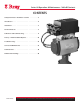
Series 6A Operation & Maintenance – Installation Installation Mounting to an Actuator All Bray S6A positioners are suitable for mounting on Bray pneumatic actuators with the use of a standard mounting bracket. With proper mounting hardware, the S6A positioner can be installed onto other linear or quarter turn pneumatic actuators.
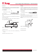
Series 6A Operation & Maintenance – Field Connections Field WIRING Each S6A is provided with two conduit entries for power/incoming analog signal of the main unit and any optional modules. Please refer to the wiring diagrams referenced in this document when connecting the positioner and any optional modules. It is essential to install the optional modules before connecting the positioner electrically.
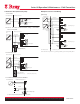
10 2 3 4 5 4 ... 20 mA J Series 6A Operation & Maintenance – Field Connections 6 II. Hazardous Area (Intrinsically Safe) 7 – A. Two Wire Non-hazardous area Hazardous area, Zone 1 4 to 20 mA EEx Multiple Positioners Field Wiring 8 9 BE1 = Binary Input 10 6 18 ... 30 Intrinsically safe power source Split Range Auxiliary power Positioner + 7 8 V9 10 1) 2 3 – 4 # 5 Binary input 1 + 6 B. and C. Two Wire Connection When Using a 2/3/4 7 0/4 ...
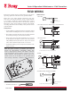
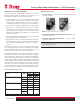
Series 6A Operation & Maintenance – Field Connections Connecting Pneumatic Supply Lines 1. Refer to the Technical Data portion of this manual for specifications regarding air quality. If required, connect the pressure gauge block for supply air and actuating pressure. 2. Connect supply air to PZ. The S6A is equipped with three pneumatic connections, Y1, Y2 and PZ. PZ is for the pneumatic supply and Y1 and Y2 are used to supply the pneumatic actuator.
Series 6A Operation & Maintenance – Field Connections Restrictors Purging The S6A is equipped with air restrictors to reduce the air output to achieve actuating times of T > 1.5 s for small actuators. Restrictors 1 and 2 are used for this purpose. The S6A is equipped with a purge air switch that allows the actuator to purge air either inside of the unit or directly outside. When the enclosure is open, the purge air switch above the pneumatic terminal strip on the pneumatic block can be accessed.
Series 6A Operation & Maintenance – Field Connections Natural Gas as an Actuator Medium Optional Accessories The S6A can also be operated with natural gas as an actuator medium. When operating the positioner with natural gas, you must follow and adhere to the following safety notes: 1. Pressure Gauges – used to measure and indicate supply and actuating pressures 1. Only the “EEx ia” version of the positioner and optional modules with the “EEx ia” type of protection may be operated with natural gas.
Series 6A Operation & Maintenance – Calibration & Commissioning Calibration and Commissioning Installing a New Unit Please refer to the S6A Quick Start Guide for the Standard Unit. Replacing a Unit The S6A can be replaced in a running system where a S6A was already in use without interrupting the process. By copying and transferring the device and initialization data, it is possible to commission a replacement positioner without needing to initialize it.
Series 6A Operation & Maintenance – Calibration & Commissioning Operating Modes Configuration and initialization mode The S6A has five different operating modes described in detail below. Refer to Figure 7 to navigate between modes. Operating Mode Display P- manual operation To get to the “Configuration” mode, press the operating mode button for at least 5 seconds. You can use the “Configuration” mode to adjust the positioner individually as per your actuator and start commissioning or initialization.
Series 6A Operation & Maintenance – Calibration & Commissioning Automatic (AUT) Automatic is the standard mode. In this mode, the positioner compares the setpoint position with the actual position. The positioner moves the actuator until the control deviation reaches the configurable dead zone. A fault message is displayed if the dead zone cannot be reached.
Series 6A Operation & Maintenance – Calibration & Commissioning Overview of diagnostics Overview of Diagnostics Valuesvalues No. Abbreviation Meaning Values that can be displayed Unit Reset possible 1 STRKS Stroke number (Strokes) 0 ... 4.29E9 - X 2 CHDIR Changes of direction (Changes of Direction) 0 ... 4.29E9 - X 3 CNT Number of fault messages ( Counter) 0 ... 4.29E9 - X 4 A1CNT Number of alarms 1 (Alarm 1 Counter) 0 ... 4.
37 T7 Number of operating hours in temperature range 7 0 ... 4.29E9 Hours - 38 T8 Number of operating hours in temperature range 8 0 ... 4.29E9 Hours - 39 T9 Number of operating hours in temperature range 9 0 ... 4.29E9 Hours - 40 VENT1 Number of switching cycles of pilot valve 1 0 ... 4.29E9 - - 41 VENT2 Number of switching cycles of pilot valve 2 0 ... 4.29E9 - - 42 STORE Save the current value as "last maintenance" (press the increment button for 5 s) (Store) 1 ...
Series 6A Operation & Maintenance – Calibration & Commissioning Parameter 1) YFCT Function Type of position actuator Parameter Values Turn WAY LWAY ncSt -ncSt 2) YAGL Angle of rotation 3) 4) 5) 6) Range of Stroke Initialization (automatic) Initialization (manual) Current range of setpoint YWAY INITA INITM SCUR 7) SDIR Setpoint Setup 8) SPRA 9) SPRE 10) TSUP 11) TSDO 12) SFCT Setpoint Setpoint Setpoint Setpoint Setpoint 13) SLO …33) SL20 34) DEBA 35) YA 36) YE 37) YNRM 38) YDIR 39) YCLS 40)
Series 6A Operation & Maintenance – Calibration & Commissioning 41) YCUP 42) BIN1 2) Upper value for tight closing Function of BE1 0.0 … 99.5 … 100% Used to set the value for tight “Tight closing below” and “Tight closing above”. Factory setting is “99.5” Normally Open Functions while in binary input mode.
Series 6A Operation & Maintenance – Calibration & Commissioning 53) FSTI 54) FSVL Monitoring Period for setting the safety seating Safety Setpoint 55) STNR Station Number 56) IDENT Device operating mode (ID No.) Parameter A. PST Function Partial Stroke Test 0 … 100 (s). Once this set value expires the positioner switches to its safety position. (Factory defined at 0) 0.0 … 100.0 (%). Default value of the safety position. (Factory setting is 0%) Independent value for each station.
Series 6A Operation & Maintenance – Calibration & Commissioning F. ZERO F1.LEVEL1 F2.LEVEL2 F3.LEVEL3 G. OPEN G1.LEVEL1 G2.LEVEL2 G3.LEVEL3 H. TMIN H1.TUNIT H2.LEVEL1 H3.LEVEL2 H4.LEVEL3 J. TMAX J1.TUNIT J2.LEVEL1 J3.LEVEL2 J4.LEVEL3 L. STRK L1.
Series 6A Operation & Maintenance – Installable Options Factory or Field Installable Options The S6A comes standard with guides beneath the motherboard so that optional modules can be added. Tools Needed: Device features The Iy module is: • Single channel • Potentially isolated from the standard controller. • T2O Torx • Phillips Screwdriver Step A To install any of the optional modules proceed as follows: 1. Disconnect electrical power from the supply to the positioner 2.
Series 6A Operation & Maintenance – Installable Options Installing the Mechanical Limit Switch Module Notice A pin in the actuating disc bearing is pressed. Align this pin before it touches the special screw. You must rotate the actuating disc bearing and the special screw simultaneously so that the pin is inserted into the special screw. An insulating cover is provided over the mechanical limit switch module. Place the insulating cover to one side under the motherboard seat on the container wall.
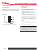
Series 6A Operation & Maintenance – Installable Options Non Hazardous Area Installing the Alarm Module Hazardous Area, Zone 1 Intrinsically safe switching amplifier to DIN EN 60947-5-6 Mechanical limit switch module 6DR4004-6K 2K1 + max. DC 8,2 V EEx + Umax. DC 30 V Imax 100 mA = + = Umax. DC 30 V Imax 100 mA 31 32 10K 41 42 51 52 Fault message Limit value A1 Limit value A2 Alarm Unit Figure 11.
Series 6A Operation & Maintenance – Installable Options Proceed as follows to install the alarm unit: Installing the Slotted Initiator Alarm Unit 1. Perform Step A to remove the module cover 2. Slide the alarm unit below the motherboard in the module rack. Ensure that you slide it up to the end stop. 3. Connect the module to the motherboard. For this purpose, use the 8-pole flat ribbon cable provided. 4.
Series 6A Operation & Maintenance – Installable Options Setting The Limits Of The Slotted Initiator Alarm Unit Notice A pin in the actuating disc bearing is pressed. Align this pin before it touches the special screw. You must rotate the actuating disc bearing and the special screw simultaneously so that the pin is inserted into the special screw. 7. An insulating cover is provided over the SIA unit. Place the insulating cover to one side under the motherboard seat on the container wall.
Series 6A Operation & Maintenance – Installable Options Installing the EMC Filter Module EMC Module Function You will require the EMC filter module if you use an external position sensor on the positioner, e.g. a potentiometer or a noncontacting position sensor. The EMC filter module forms the interface between external position sensors and the motherboard of the positioner. This module protects the positioner from electromagnetic effects.
Series 6A Operation & Maintenance – Troubleshooting Troubleshooting During operation of the positioner, a few important values and parameters are continually monitored. In configuration mode, you can configure that monitoring so that the fault message output will be activated if, for instance, a limit is exceeded.
Series 6A Operation & Maintenance – Troubleshooting Remedial Measures Table 1 Fault profile (symptoms) Possible cause(s) Remedial measures Positioner remains in “RUN 1”. Initialization started from the end position A waiting time of up to 1 minute is essential Positioner remains in “RUN 2”. Transmission ratio selector and parameter 2 do Check settings: see leaflet: “Device view (7)” picture as well not match the actuator type. as parameters 2 and 3 Positioner remains in “RUN 3”.
Series 6A Operation & Maintenance – Troubleshooting Remedial Measures Table 4 Fault profile (symptoms) Possible cause(s) Remedial measures Sticking friction of the packing gland from the Reduce friction or increase dead zone of positioner (paramcontrol valve or actuator too large eter ”dEbA”) until the oscillation stops In stationary automatic mode (constant setpoint) and in manual Looseness (play) in the positioner/actuator/con- Part-turn actuator: Check for firm seating of set screw on coumode, both p
Series 6A Operation & Maintenance – Service and Maintenance Service and Maintenance The S6A is maintenance-free to a large extent. Screens are installed in the pneumatic connections of the positioners to protect them from debris. If there are dirt particles in the pneumatic auxiliary power supply, they damage the screens and hamper the function of the positioner.
Series 6A Operation & Maintenance – Technical Data Technical Data 1. Basic Units Technical specifications SIPART PS2 Basic device without Ex protection Basic device with Ex d protection (flameproof enclosure) Basic device with Ex ia/ib protection Basic device with Ex n/ dust protection 3-/4-wire device (terminals 2/4 and 6/8) (6DR52.. and 6DR53..) • Power supply UH 18 ... 35 V DC 18 ... 30 V DC • Current consumption IH (UH - 7.
Series 6A Operation & Maintenance – Technical Data Technical specifications SIPART PS2 PA Basic device without Ex protection Basic device with Ex d protection (flameproof enclosure) Basic device with Ex ia/ib protection Basic device with Ex n/ dust protection Explosion protection as per ATEX Without Ex d II 2 G Ex d II C T4/T5/T6 Ex ia/ib II 2 G Ex ia/ib II C T6 Ex n II 3 G Ex nA nL[nL] IIC T6 Dust II 3 D Ex tD A22 IP66 T100°C Mounting location Zone 1 Permissible ambient temperature for -30 ...
Series 6A Operation & Maintenance – Technical Data Technical specifications SIPART PS2 PA Basic device without Ex protection Basic device with Ex d protection (flameproof enclosure) Basic device with Ex ia/ib protection Basic device with Ex n/ dust protection Communication Layers 1 and +2 according to PROFIBUS PA, transmission technology according to IEC 1158-2; slave function; layer 7 (protocol layer) according to PROFIBUS DP, EN 50170 standard with the extended PROFIBUS functions (all data acyclic,
Series 6A Operation & Maintenance – Technical Data Technical specifications SIPART PS2 FF Basic device without Ex protection Basic device with Ex d protection (flameproof enclosure) Basic device with Ex ia/ib protection Basic device with Ex n/ dust protection Explosion protection as per ATEX Without Ex d II 2 G Ex d II C T4/T5/T6 Ex ia/ib II 2 G Ex ia/ib II C T6 Ex n II 3 G Ex nA nL[nL] IIC T6 Dust II 3 D Ex tD A22 IP66 T100°C Mounting location Zone 1 Permissible ambient temperature for -30 ...
Series 6A Operation & Maintenance – Technical Data Technical specifications SIPART PS2 FF Basic device without Ex protection Basic device with Ex d protection (flameproof enclosure) Basic device with Ex ia/ib protection Basic device with Ex n/ dust protection Communication Communications group and class According to technical specification of the Fieldbus Foundation for H1 communication Function blocks Group 3, Class 31PS (publisher, subscriber) 1 resource block (RB2) 1 analog output function block (
Series 6A Operation & Maintenance – Technical Data Technical specifications SIPART PS2 (all versions) Weight, basic device General data Range of stroke (linear actuators) 3 ... 130 mm (0.12 ... 5.12 inch) (angle of positioner shaft 16 ... 90°) Angle of rotation (part-turn actuators) 30 ...
Series 6A Operation & Maintenance – Technical Data Technical specifications SIPART PS2 Basic device without Ex protection Basic device with Ex d protection (flameproof enclosure) Basic device with Ex ia/ib protection Basic device with Ex n/ dust protection Explosion protection ATEX - Ex d II 2 G Ex d II C T6 Ex ia/ib II 2 G Ex ia/ib II C T6 Ex n II 3 G Ex nA nL[nL] IIC T6 Dust II 3 D Ex tD A22 IP66 T100°C Mounting location - Zone 1 Permissible ambient temperature for -30 ...
Series 6A Operation & Maintenance – Technical Data 2. Optional Models Technical specifications Add-on modules Without Ex protection/ with Ex d protection With Ex ia/ib protection With Ex n/dust protection Ex protection acc. to ATEX – II 2G Ex ia/ib II C T4/T5/T61) Ex n II 3 G Ex nA nL[nL] IIC T6 Dust II 3 D Ex tD A22 IP66 T100°C Mounting location – Zone 1 Zone 2/22 Permissible ambient temperature for operation (For devices with Ex protection: Only in conjunction with the basic device 6DR5... -.
Series 6A Operation & Maintenance – Technical Data Technical specifications Add-on modules Without Ex protection/ with Ex d protection SIA module Limit transmitter with slot-type initiators and alarm output 6DR4004-8G (not for Ex d version) With Ex ia/ib protection 6DR4004-6G 2-wire connection Limit transmitter A1, A2 Ex protection With Ex n/dust protection Without Connection II 2 G Ex ia/ib IIC T6 II 3 G Ex nA nL [nL] IIC T6 2-wire system to EN 60947-5-6 (NAMUR), for switching amplifier to be co
Series 6A Operation & Maintenance – Technical Data Technical specifications Add-on modules Without Ex protection/ with Ex d protection Iy module 6DR4004-8J With Ex ia/ib protection 6DR4004-6J DC output for position feedback 2-wire connection 4 ... 20 mA, short-circuit-proof 3.6 ... 20.5 mA Rated signal range Total operating range Power supply UH +12 ... +35 V +12 ... +30 V External loads RB [kΩ] ≤ (UH [V] - 12 V) /i [mA] ≤ 0,3 % ≤ 0.1 %/10 K (≤ 0.
Series 6A Operation & Maintenance – Dimensional Drawings Dimensional Drawings Dimensional drawings All air connections 185 (7.28) 4) 72 (2.83)1) 29.5 29.5 (1.16) (1.16) 95 (3.74)2) 50 x 4 (1.97 x 0.16) x M6 11.2 (0.44) 29.5 (1.16) G 1/4 or 1/4 NPT 59 (2.32) 84 (3.31) 50 x 4 (1.97 x 0.16) x M6 All air connections 185 (7.28) 4) 11.2 (0.44) G 1/4 or 1/4 NPT 96.6 (3.80)3) Stainless steel version, values: M20 x 1.5 1) 2) 3) 4) 74 (2.91) 99 (3.89) 98 (3.
G 1/4 or 1/4 NPT 96.6 (3.80)3) Stainless steel version, values: M20 x 1.5 1) 2) 3) 4) 74 (2.91) 99 (3.89) 98 (3.86) Dimension at electrical connection ½-14 NPT (with adapter) 203 mm Series 6A Operation & Maintenance – Dimensional Drawings Makrolon and stainless steel enclosure double acting (top), aluminum enclosure single acting (center), Makrolon and aluminum enclosure (bottom), dimensions in mm (inch) 10.25 (0.4) 12 (0.47) 1) M6, 8 (0.31) deep (2x) 60 (2.
R CONTROLS A Division of BRAY INTERNATIONAL, Inc. 13333 Westland East Blvd. Houston, Texas 77041 281/894-5454 FAX 281/894-9499 www.bray.com Bray® is a registered trademark of Bray International, Inc. © 2011 Bray International. All rights reserved.