
Installation Manual

3 Installer Guide
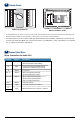
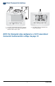
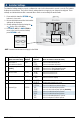
Provide Power
C
24VAC Power Terminal (C)
2
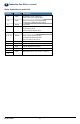
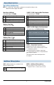
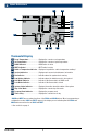
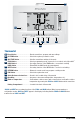
Wiring Terminations for model 5020
Connect Your Wires
3
+
+
• For 24 Volt AC power, you must connect the common side of the transformer to the C terminal on the thermostat sub-base. In
dual transformer installations, the transformer common must come from the cooling transformer.
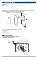
• For battery power, insert the 2 supplied “AA” type alkaline batteries into the battery compartment located in the rear
housing of the thermostat. Make sure to position the Positive (+) and Negative (-) sides of the batteries correctly with
the +/- symbols in the battery compartment.
Batteries Installed as Shown
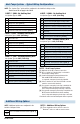
Terminal Function Description
Rc Input 24 Volt AC Cooling Transformer
(Dual Transformer Systems Only)
Rh Input Power Connection (24 Volt AC Heating
Transformer or Millivolt Power Source)
G Output Fan Control
W1 / E Output (W1) Conventional Heat Relay
(E) Auxiliary/Emergency Heat
O / B / V3 Output (O) Cool Active Reversing Valve
(B) Heat Active Reversing Valve
(V3) Zone Valve Power Close
Y1 Output Compressor Relay
C Input 24 Volt AC Transformer Common
S1
S2
Input Optional Remote Sensor (indoor or outdoor)