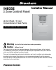
® 140332 Installer Manual 3 Zone Control Panel Up to 3 Heat / 2 Cool Conventional or Heat Pump Store this manual for future reference. Warning Caution Read all of the instructions before proceeding Voltage Hazard Can cause electrical shock or equipment damage. Always turn off power to the heating/ air conditioning system prior to installing or adjusting the expandable zone panel. Wire the entire panel before applying transformer power.
Table of Contents 1 Specifications.....................................................................................................................2 2 Suitable Mounting Locations...............................................................................................3 3 Wiring.............................................................................................................................4-9 4 Configuration.................................................................................
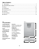
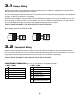
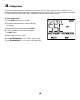
2 Suitable Mounting Locations Mount the Zone Panel near the HVAC equipment. The panel can be mounted in any orientation on a wall, stud, roof truss, or the return-air plenum. For appearance, mount the panel level. Remove the panel cover and use the base as a template to drill mounting holes (see Figure 2). Attach the panel with appropriate screws. Use mounting anchors as needed for drywall or plaster installations.
3 Wiring the Panel ZONE 1 Always turn off power to the heating/air conditioning system prior to installing or adjusting the Zone Panel. Wire the entire panel before applying transformer power. Use the following general wiring instructions for all systems. Specific wiring will vary depending on the equipment and type of system (conventional or heat pump). NOTE: Up to 2 wires can be inserted into each terminal. To release wires, press down on top of wiring terminal and gently pull out wire(s).
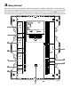
ZONE PANEL WIRING TERMINALS Terminal PANEL POWER 1 DAMPERS 2 SUPPLY AIR OUTDOOR AIR 3 4 EQUIPMENT Qty.
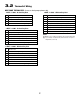
3.1 Damper Wiring Always turn off power to the heating/air conditioning system prior to installing or adjusting the zone panel. Wire the entire panel before applying transformer power. Use the following general wiring instructions for all systems. Specific wiring will vary depending on the equipment and type of system (conventional or heat pump). Install the system dampers using the instructions provided by the manufacturer.
3.
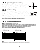
3.3 Plenum Optional Supply Air Sensor Wiring To provide high/low limit protection, install the optional supply air sensor in the supply air plenum at least 2-3 feet after the heat exchanger and coil. Make sure there are no zone dampers before the supply air sensor. Connect the supply air sensor to the zone panel as shown. SA1 SA2 3.4 Transformer Wiring Install the transformer using the instructions provided by the manufacturer. Size the transformer to the damper requirements.
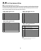
3.6 Heat Pump Equipment Wiring NOTE: For Conventional Systems, see Section 3.5 Connect a single or multi-stage heat pump system to the zone panel as shown. A conventional thermostat may be used with a heat pump system, however, emergency heat will be controlled by the panel emergency heat switch or the optional remote emergency heat switch. For a single stage system, the auxiliary heat control is not used.
4 Configuration Use the following instructions to configure the zone panel. The zone panel is factory set for a 1 Heat / 1 Cool Conventional System with Conventional Thermostats (Heat Call on W, Cool Call on Y). If the zone panel is installed on other systems, you will need to make configuration changes described in this section. To start configuration: 1. Press SETUP and hold for 3 seconds. 2. The panel backlight will turn on and the display will change. 3. Change setting if needed by pressing SELECT. 4.
4 Configuration The configuration settings must be properly set in order for this zone panel to operate correctly. The Installer Settings will automatically adjust so that settings that do not apply to this installation will be skipped. All settings are shown below with comments. No.
No.
5 System Checkout After the wiring and configuration is complete, built in automatic zone panel tests may be used to verify equipment, damper, and panel operation. To start the panel Test Mode: 1. Ensure all wiring is complete and power has been applied to the main and expansion panels 2. Press TEST for 3 seconds and release 3. Press SELECT to turn the test on and off 4. Press NEXT to move on to the next test 5.
Fan Stage(s) Test ON or OFF This test turns on all fan stages and commands all dampers to open. Press SELECT to test or NEXT to advance to the next test. Damper Control Test PO or PC This test powers all dampers open or closed. Press SELECT to test or NEXT to advance to return to first test. 6 Operation The Zone Panel has LED’s and a built-in display to tell the installer and the system owner the current operating mode of the panel.
LED COLOR INDICATION R Red 24 VAC available to Thermostat Y1 Yellow Thermostat First Stage Compressor Call Y2 Yellow Thermostat Second Stage Compressor Call W1/E/AUX White Thermostat Call for W1 or E or AUX W2/O/B White Thermostat Call for W2, O or B G Green Thermostat Fan Call Thermostat LED’s (3 Positions) Damper LED’s (3 Positions) Power Close / Power Open Red / Green Red On Damper Closed; Green on Damper Open No light when wiring short detected In addition to LED’s, the zon
FAN CALLS Number of fan calls currently being serviced. Check the panel LED if it is necessary to determine exactly which zones are Equipment Plenum Temperature (PLENUM TEMP) When the optional plenum air temperature sensor is installed and enabled, the zone panel will display the Plenum temperature in the range of 30 - 200˚ F (1 - 93˚C). Plenum Temperatures outside this range indicate an equipment error. See Section 7 Error Conditions for a further explanation.
7 Error Conditions The zone panel continually monitors various components of the zone system and will display a message when the following monitored conditions are detected. COOL DISABLE Cooling is disabled when Emergency Heat has been selected on a heat pump system Selecting emergency heat from a thermostat (See Installer Option 21) in heat mode will disable compressor cooling in all zones.
Plenum Sensor Bad Displayed when an error has been detected with the plenum sensor. This error must be corrected by servicing the zone panel plenum sensor. If the sensor is not operating correctly, the zone panel will not call for additional stages of heating or cooling. Outdoor Sensor Bad (ODTSENS) Displayed when an error has been detected with the outdoor sensor. This error must be corrected by servicing the zone panel outdoor sensor.