
Troubleshooting guide
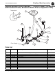

Bradley Washfountains Parts and Service Guide
50 Bradley Corporation • 215-1370 Rev. M; EN 08-003
1/7/08
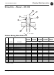
Troubleshooting AccuZone Infrared
1. Check the lens — (windows) of the sensor(s) to make sure they are not pushed in, covered with debris or
scratched. Scratches can distort the view of the sensor. Clean if dirty or replace if damaged. If lens
needs to be replaced use Lord acrylic adhesive 406/19 or an epoxy glue to glue the lens in place and seal
from outside moisture. Clean off excess glue and allow to dry.
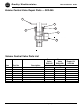
2. Verify there is power — to the transformer and verify there are 24 volts coming from the trans-
former.
3.Unplug the transformer
— harness from the module harness, disconnect module harness from the sole-
noid valve. Plug the transformer directly to the solenoid valve. If there is 24 volts, and the solenoid is
working properly, water will turn on and run continuously. If the water does not turn on and you know
there are 24 volts coming from the transformer, the solenoid will have to be replaced.
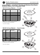
4. If the water
does not turn off or
dribbles
— after disconnecting the power, there is debris at the
diaphragm of the solenoid valve. Take apart the solenoid valve to check for debris which may be keeping
the valve open. Unscrew the 3 or 4 screws that hold the solenoid to the lower valve body. (The S27-250
solenoid valve does have a screen in the inlet end. Check and make sure that screen is clean.) Clean the
diaphragm and make sure the small hole in the diaphragm is not plugged. This small hole is very hard to
see. Hold it up to the light to find the hole. It is located about half way between the OD and the ID. Soak
the diaphragm in vinegar for 15 to 20 minutes and rinse well with water to remove mineral deposits.
Reassemble valve and test again with power from the transformer.
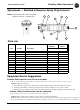
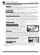
5. If the solenoid is working
, — take the cover off the module and check to make sure all leads are connect-
ed properly and all sensors are plugged onto the circuit board.
6. Make sur
e the output and input wires
— from the circuit board are not loose or broken off.
7. Check the MOV
(metal oxide Varistor) — on the circuit board
for discoloration. This varistor can be burned out from power surges
and lightening strikes. The discoloration will be evident if the
varistor is burned out. If the varistor is burned out, the circuit
board will have to be replaced. Note: Do not use the part number
printed on the circuit board, that is a bare board.
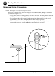
8. Unplug all sensors
— from the circuit board (remembering where
the wires go). Plug in one sensor at a time. If sensor works prop-
erly, continue on to the next sensor. Test all sensors individually. If some sensors work and some do not,
plug the sensors not working into the location where the sensors do work. This will confirm that the sensor
is dead or there is a problem in the circuit board. It is possible that an on site electrical surge or a lighten-
ing strike could burn out a sensor, all sensors or an individual circuit on the circuit board. If you find any
in this condition, add a good surge protection device to the circuit to avoid future problems. Note: Make
sure your sensor has the foam strip properly applied to the center of the sensor.
9. If an individual station is not working
, — loosen the screws on the
sensor bracket and reposition to make sure the sensor is properly posi-
tioned in front of the lens (window). The sensor should not be seeing
any edges of the module opening.
10.Replace sensors as necessar
y. — Order assembly # S83-039.
11.If a new installation
, — and the above checks do not resolve the prob-
lem, check the wiring of the sensor plugs.
If you need further assistance, please call your local Bradley Representative.
Please call us at 1-800-Bradley if you need the name and telephone number of your local Bradley
Representative.
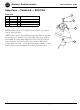
Output
wires to
solenoid
Input wires from transformer
Varistor
Sensor with plug
S83-039
Sensor assembly includes the disconnect
terminal and foam spacer on face of sensor.
The bracket is not included as shown.
Foam Spacer