
Troubleshooting guide
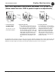

Parts and Service Guide Bradley Washfountains
Bradley Corporation • 215-1370 Rev. M; EN 08-003 35
1/7/08
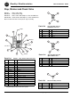
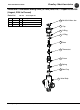
Foot Valve Adjustment Instructions (November 1973 to Jan. 2003)
(Valves made from Jan. 2003 to present require no adjustments)
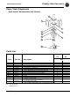
Adjusting Needle
Spring
Seat
Needle
Valve
Orifice
Plunger
Operating
Lever
O Rings
Relief
Ports
Flexible Rubber
Ring (Closed)
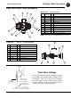
I. CLOSED POSITION:
PLUNGER SEATED.
NO WATER FLOW.
(Needle Valve is used to
prevent water hammer)
II. OPENING POSITION:
a)Valve actuated - plunger pushed off seat
— water flows through seat to sprayhead.
b)As opening cycle starts and water within
the hollow plunger assembly is pushed out
through restricted needle valve orifice, pres-
sure is relieved through ports covered with
flexible rubber ring, allowing valve to open
easily. Rubber ring acts as check valve,
preventing back flow through parts which
would defeat slow closing feature of the
valve.
III.CLOSING POSITION:
As operating lever is released, plunger
moves back towards seat, pushed by the
spring, but retarded by flow of water to
sprayhead and vacuum created by
displacement of water behind plunger.
Bypass water moving through needle
valve orifice fills vacuum and helps to
return plunger to seat. Speed of closure
controlled by volume of water allowed
through needle valve.
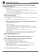
The adjusting needle controls the closing, or shut off speed of valve. Turning the adjusting needle clockwise retards closing. This
adjustment corrects water hammer problems. Turning the adjusting needle counterclockwise speeds closing. Any needle valve
adjustments should be slight, not more than 1/4 turn at a time until the desired rate of shut off is achieved.