
Specifications

TDB3108, WF3208 Installation
10 1/23/2013 Bradley • 215-1471 Rev. F; ECN 13-00-001
4a
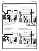
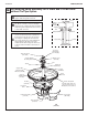
Air Metering Valve Assembly for A Drain and O Drain Units
without Tie Pipe Option continued...
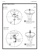
D
Place the actuator module assembly on top of
sprayhead. Rotate until actuator module locks in
with tie bar. Drop 1/8" diameter tube down to valve
assembly and connect to the air valve.
Skip to step F for units without soap.
E
For units with soap option, install the spacer, soap
dispenser and cover using the third tie rod (8-5/8"
long) and second coupling nut as shown. Secure
with acorn nut and set screw.
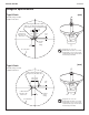
F
Secure actuator module cover and top cover
with sprayhead restraining bracket, acorn nut
and set screw.
G
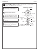
FOR O UNIT: Install 1/2" nominal copper tubing
supply lines (pass them through holes in cover
down through support column) and connect to
stops using suitable fittings.
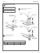
Unit with "O" Drain and Actuator Module
Shown, Also Available with "A" Drain
Top
Cover
Soap
Dispenser
8-5/8" Tie Rod
Spacer
Coupling
Nut
Module
Cover
4-1/4" Tie Rod
Actuator Module
Assembly
(S65-134)
Coupling
Nut
Tie Bar
Sprayhead
(S05-054)
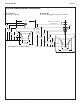
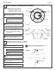
Standard Support Tube
(S57-005)
TAS/Juvenile Support Tube
(S57-006)
Standard Tie Rod
21-5/8"
Juvenile Tie Rod
18-1/8"