
Installation manual


Terreon® 54" Circular Deep Bowl Washfountain with Air Metering Valve
TDB3108, WF3208 Installation Instructions
Bradley Corporation • 215-1471 Rev. E; EN 06-915B16 4/6/2007
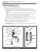
1/8" TEE
S53-046
TO ACTUATOR
CONNECTOR
(2) PLACES
TUBE CONNECTOR
169-890
AIR VALVE TIMER
ADAPTER 198-008
AIR VALVE
S07-044
THERMOSTATIC
MIXING VALVE
ASSEMBLY
S67-597
STOP/CHECK
VALVE
3/8" NPT x
1/2" O.D. TUBE
269-639
1/2" DIA. TUBE
TO SPRAYHEAD
REDUCER
169-059
3/8" NIPPLE
113-006EC
CHECK VALVE
269-1140
FLEXIBLE
HOSE
FILTER WASHER
VOLUME CONTROL
S02-045
Figure 10a
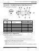
Figure 10b
RELEASE
BUTTON
GRIPPING
RIDGE
LOCKING
SLOPE
TUBING
TUBE
STOP
SEALING
RING
Installation Instructions continued . . .
Step 5: Valve and Tubing Connections
NOTE: Flush supply lines before making connections.
1. Connect 1/2" dia. tubing to tee and solenoid assembly, two places. The male connector
(Figure 10b) for the valve assembly will remain tight and leakproof when tubing is cut and
installed properly. Follow the procedures below when installing tubing to ensure that you achieve
a leakproof seal.
• Using a sharp razor, cut tubing squarely and remove any burrs. DO NOT pinch or crush end of
tubing.
• Loosen nut on fitting. Moisten end of tube and push into fitting until it is firmly seated.
Tighten nut to secure tube to fitting (make sure nut is securely tightened).
• If connector leaks, reseat tubing according to above procedure. If leaking persists, replace
male connector, or call your Bradley representative for assistance.
2. Hang valve assembly on pedestal bracket (see Figure 11 on page 17). Use wire tie to secure valves.
NOTE: For “O” and “B” units (overhead supplies) skip steps 3 through 5.
3. Connect the 1/2" NPT female end of the stop/check valves to the rough-ins.
4. Attach flexible hosing to thermostatic mixing valve, two places.
5. Insert the filter washers (provided) into the swivel nut at the end of the supply hoses and connect
to the stop/check valves.
Valve Assembly S08-373